Projeto eletrônico: Gerenciamento de uma matriz de LED com Arduino
O projeto consiste em gerenciar um array de LEDs baseado em Arduino 8X8 usando o circuito MAX7219CNG. O projeto eletrônico usa uma biblioteca para o gerenciamento do circuito MAX7219CNG com um link SPI. Este mini projeto destaca o uso da biblioteca com outras funções secundárias (turno, conversão, …).
Conteudo
Operação de matriz LED 8 × 8
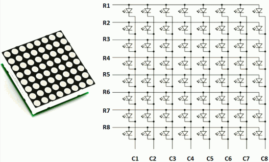
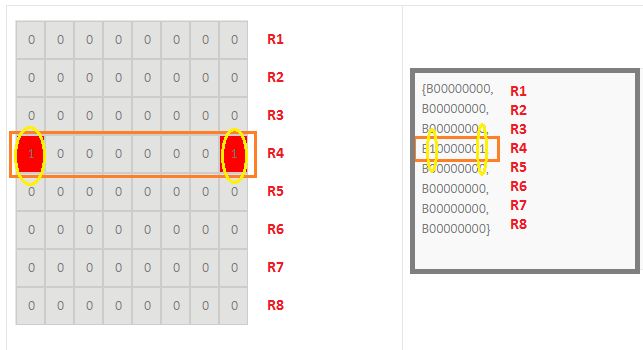
A matriz de LED consiste em 8 linhas e 8 colunas. A matriz pode ser comparada a uma matriz 1D de 8 elementos, cada elemento da matriz é codificado em 8 bits Ex B00001111 ou 0x0F, na figura abaixo ilustra a transição de uma matriz 8 × 8 para uma matriz em 8 elementos de digite Bye ou Unsigned char. Veremos a seguir a função que permite exibir o código na matriz 8 × 8.
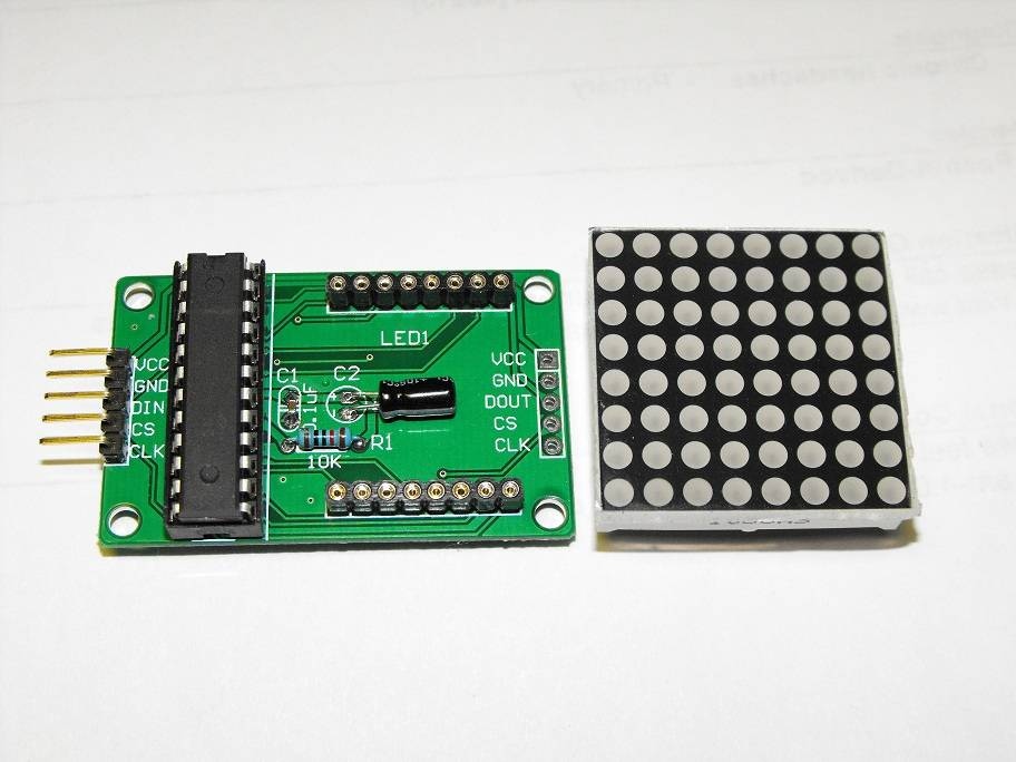
O módulo usado é baseado no MAX7219 com um link serial para dados. O barramento SPI é composto por três fios:
CS: Chip Select para ativação do modelo
CLK: o relógio síncrono para dados. O relógio define a velocidade da transmissão de dados seriais
DIN: dados seriais de 8 bits
Mais detalhes sobre a transmissão serial: SPI
Link para um aplicativo gratuito para gerenciar uma matriz 8×8 de LEDs
Comentários do programa
void int2BitArray(unsigned char dataIn,unsigned char taille,byte *dataArray)
A função int2BitArray é usada para converter uma variável char em uma matriz em N bits (N=8 bits)
Ex1: para dataIn=10, taille=8 então a variável de saída dataArray[8] = {0,0,0,0,1,0,1,0] (equivalente a B00001010)
Ex2: dataIn=127, taille=8, então a variável de saída dataArray[8] = {0,1,1,1,1,1,1,1] (equivalente a B011111111)
void DataShiftArray(unsigned char NumShift, unsigned char taille, byte *DataIn, byte *DataOutShift)
A função DataShiftArray é usada para deslocar para a direita uma matriz de comprimento “tamanho” de bits (matriz binária) DataIn, o resultado é armazenado e retornado na matriz DataOutShift. No início, a matriz DataOutShift é considerada inicializada em 0.
Ex: NumShift=3, taille=8, DataIn[8]={1,1,1,1,0,0,0,0} e DataOutShift[8]={0,0,0,1,1,1,1,0}.
O objetivo da função é deslocar um objeto na matriz 8×8 de LEDs.
As funções disponíveis na biblioteca LedControl.h (MAX7219/MAX7221)
private :
        /* The array for shifting the data to the devices */
        byte spidata[16];
        /* Send out a single command to the device */
        void spiTransfer(int addr, byte opcode, byte data);

        /* We keep track of the led-status for all 8 devices in this array */
        byte status[64];
        /* Data is shifted out of this pin*/
        int SPI_MOSI;
        /* The clock is signaled on this pin */
        int SPI_CLK;
        /* This one is driven LOW for chip selectzion */
        int SPI_CS;
        /* The maximum number of devices we use */
        int maxDevices;

    public:
        /*
         * Create a new controler
         * Params :
         * dataPin		pin on the Arduino where data gets shifted out
         * clockPin		pin for the clock
         * csPin		pin for selecting the device
         * numDevices	maximum number of devices that can be controled
         */
        LedControl(int dataPin, int clkPin, int csPin, int numDevices=1);

        /*
         * Gets the number of devices attached to this LedControl.
         * Returns :
         * int	the number of devices on this LedControl
         */
        int getDeviceCount();

        /*
         * Set the shutdown (power saving) mode for the device
         * Params :
         * addr	The address of the display to control
         * status	If true the device goes into power-down mode. Set to false
         *		for normal operation.
         */
        void shutdown(int addr, bool status);

        /*
         * Set the number of digits (or rows) to be displayed.
         * See datasheet for sideeffects of the scanlimit on the brightness
         * of the display.
         * Params :
         * addr	address of the display to control
         * limit	number of digits to be displayed (1..8)
         */
        void setScanLimit(int addr, int limit);

        /*
         * Set the brightness of the display.
         * Params:
         * addr		the address of the display to control
         * intensity	the brightness of the display. (0..15)
         */
        void setIntensity(int addr, int intensity);

        /*
         * Switch all Leds on the display off.
         * Params:
         * addr	address of the display to control
         */
        void clearDisplay(int addr);

        /*
         * Set the status of a single Led.
         * Params :
         * addr	address of the display
         * row	the row of the Led (0..7)
         * col	the column of the Led (0..7)
         * state	If true the led is switched on,
         *		if false it is switched off
         */
        void setLed(int addr, int row, int col, boolean state);

        /*
         * Set all 8 Led's in a row to a new state
         * Params:
         * addr	address of the display
         * row	row which is to be set (0..7)
         * value	each bit set to 1 will light up the
         *		corresponding Led.
         */
        void setRow(int addr, int row, byte value);

        /*
         * Set all 8 Led's in a column to a new state
         * Params:
         * addr	address of the display
         * col	column which is to be set (0..7)
         * value	each bit set to 1 will light up the
         *		corresponding Led.
         */
        void setColumn(int addr, int col, byte value);

        /*
         * Display a hexadecimal digit on a 7-Segment Display
         * Params:
         * addr	address of the display
         * digit	the position of the digit on the display (0..7)
         * value	the value to be displayed. (0x00..0x0F)
         * dp	sets the decimal point.
         */
        void setDigit(int addr, int digit, byte value, boolean dp);

        /*
         * Display a character on a 7-Segment display.
         * There are only a few characters that make sense here :
         *	'0','1','2','3','4','5','6','7','8','9','0',
         *  'A','b','c','d','E','F','H','L','P',
         *  '.','-','_',' '
         * Params:
         * addr	address of the display
         * digit	the position of the character on the display (0..7)
         * value	the character to be displayed.
         * dp	sets the decimal point.
         */
        void setChar(int addr, int digit, char value, boolean dp);
};
Exemplo de um programa da biblioteca
#include "LedControl.h"
/*
Now we need a LedControl to work with.
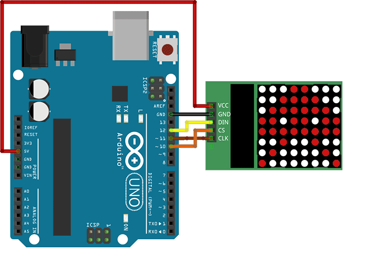
***** These pin numbers will probably not work with your hardware *****
pin 12 is connected to the DataIn
pin 11 is connected to the CLK
pin 10 is connected to LOAD
We have only a single MAX72XX.
*/
LedControl lc=LedControl(12,11,10,1);
/* we always wait a bit between updates of the display */
unsigned long delaytime=100;
void setup() {
/*
The MAX72XX is in power-saving mode on startup,
we have to do a wakeup call
*/
lc.shutdown(0,false);
/* Set the brightness to a medium values */
lc.setIntensity(0,8);
/* and clear the display */
lc.clearDisplay(0);
}
/*
This method will display the characters for the
word "Arduino" one after the other on the matrix.
(you need at least 5x7 leds to see the whole chars)
*/
void writeArduinoOnMatrix() {
/* here is the data for the characters */
byte a[5]={B01111110,B10001000,B10001000,B10001000,B01111110};
byte r[5]={B00111110,B00010000,B00100000,B00100000,B00010000};
byte d[5]={B00011100,B00100010,B00100010,B00010010,B11111110};
byte u[5]={B00111100,B00000010,B00000010,B00000100,B00111110};
byte i[5]={B00000000,B00100010,B10111110,B00000010,B00000000};
byte n[5]={B00111110,B00010000,B00100000,B00100000,B00011110};
byte o[5]={B00011100,B00100010,B00100010,B00100010,B00011100};
/* now display them one by one with a small delay */
lc.setRow(0,0,a[0]);
lc.setRow(0,1,a[1]);
lc.setRow(0,2,a[2]);
lc.setRow(0,3,a[3]);
lc.setRow(0,4,a[4]);
delay(delaytime);
lc.setRow(0,0,r[0]);
lc.setRow(0,1,r[1]);
lc.setRow(0,2,r[2]);
lc.setRow(0,3,r[3]);
lc.setRow(0,4,r[4]);
delay(delaytime);
lc.setRow(0,0,d[0]);
lc.setRow(0,1,d[1]);
lc.setRow(0,2,d[2]);
lc.setRow(0,3,d[3]);
lc.setRow(0,4,d[4]);
delay(delaytime);
lc.setRow(0,0,u[0]);
lc.setRow(0,1,u[1]);
lc.setRow(0,2,u[2]);
lc.setRow(0,3,u[3]);
lc.setRow(0,4,u[4]);
delay(delaytime);
lc.setRow(0,0,i[0]);
lc.setRow(0,1,i[1]);
lc.setRow(0,2,i[2]);
lc.setRow(0,3,i[3]);
lc.setRow(0,4,i[4]);
delay(delaytime);
lc.setRow(0,0,n[0]);
lc.setRow(0,1,n[1]);
lc.setRow(0,2,n[2]);
lc.setRow(0,3,n[3]);
lc.setRow(0,4,n[4]);
delay(delaytime);
lc.setRow(0,0,o[0]);
lc.setRow(0,1,o[1]);
lc.setRow(0,2,o[2]);
lc.setRow(0,3,o[3]);
lc.setRow(0,4,o[4]);
delay(delaytime);
lc.setRow(0,0,0);
lc.setRow(0,1,0);
lc.setRow(0,2,0);
lc.setRow(0,3,0);
lc.setRow(0,4,0);
delay(delaytime);
}
/*
This function lights up a some Leds in a row.
The pattern will be repeated on every row.
The pattern will blink along with the row-number.
row number 4 (index==3) will blink 4 times etc.
*/
void rows() {
for(int row=0;row<8;row++) {
delay(delaytime);
lc.setRow(0,row,B10100000);
delay(delaytime);
lc.setRow(0,row,(byte)0);
for(int i=0;i<row;i++) {
delay(delaytime);
lc.setRow(0,row,B10100000);
delay(delaytime);
lc.setRow(0,row,(byte)0);
}
}
}
/*
This function lights up a some Leds in a column.
The pattern will be repeated on every column.
The pattern will blink along with the column-number.
column number 4 (index==3) will blink 4 times etc.
*/
void columns() {
for(int col=0;col<8;col++) {
delay(delaytime);
lc.setColumn(0,col,B10100000);
delay(delaytime);
lc.setColumn(0,col,(byte)0);
for(int i=0;i<col;i++) {
delay(delaytime);
lc.setColumn(0,col,B10100000);
delay(delaytime);
lc.setColumn(0,col,(byte)0);
}
}
}
/*
This function will light up every Led on the matrix.
The led will blink along with the row-number.
row number 4 (index==3) will blink 4 times etc.
*/
void single() {
for(int row=0;row<8;row++) {
for(int col=0;col<8;col++) {
delay(delaytime);
lc.setLed(0,row,col,true);
delay(delaytime);
for(int i=0;i<col;i++) {
lc.setLed(0,row,col,false);
delay(delaytime);
lc.setLed(0,row,col,true);
delay(delaytime);
}
}
}
}
void loop() {
writeArduinoOnMatrix();
rows();
columns();
single();
}
Arquivos de projeto de exemplo e outros + a biblioteca C (aqui)
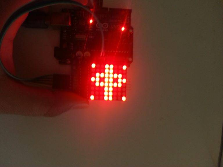
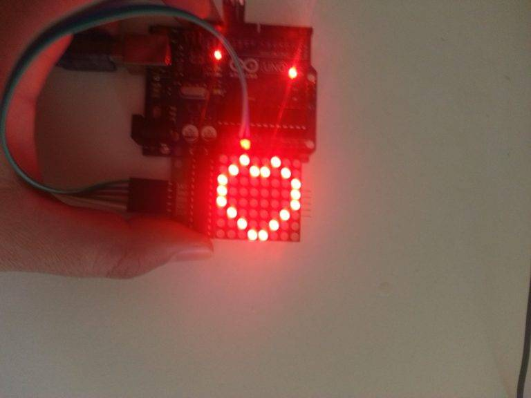
Fotos do projeto eletrônico

Conclusão
Neste artigo, mostrei como usar um LED Matrix com MAX7219 com o Arduino. Espero que você tenha achado útil e informativo. Se sim, compartilhe com um amigo que também gosta de eletrônica e de fazer coisas!
Eu adoraria saber quais projetos você planeja construir (ou já construiu) com esses Led Matrix. Se você tiver alguma dúvida, sugestão ou se achar que falta algo neste tutorial, por favor, deixe um comentário abaixo.


