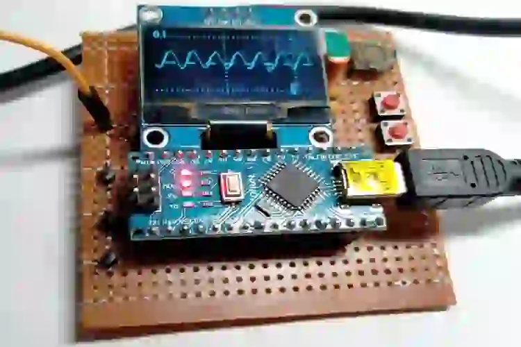
Construa um osciloscópio DIY usando Arduino Nano e tela OLED
Um osciloscópio é um dispositivo de teste eletrônico que pode monitorar a mudança constante de qualquer tensão elétrica usando gráficos bidimensionais, em que a mudança de uma ou mais tensões elétricas é colocada ao longo do tempo no eixo Y vertical. Em geral, todo hobbyista eletrônico ou alguém interessado em lidar com eletrônica precisará de um osciloscópio em algum momento. Entretanto, ele é proibitivamente caro para estudantes e amadores, e é por isso que neste artigo discutiremos como fazer um mini osciloscópio em casa usando o Arduino.
Neste artigo, construiremos um osciloscópio simples e de baixo custo baseado em Arduino com uma tela OLED de 1,3″ que pode ser usada para visualizar formas de onda com precisão. Esse projeto é inspirado no projeto Peter Balch Oscilloscope in a Matchbox. Alteramos alguns códigos e hardware para atender às nossas necessidades.
Materiais necessários para construir um osciloscópio baseado em Arduino
Os seguintes componentes são necessários para fazer esse mini osciloscópio portátil usando o Arduino Nano.
|
Quantidade |
Valor |
Dispositivo |
Pacote |
Peças |
Descrição |
|
2 |
Interruptor tátil |
Botões |
TH |
S1, S2 |
Interruptor tátil / Botões |
|
1 |
Arduino Nano |
Microcontroller |
ARDUINO_NANO |
ARDUINO_NANO1 |
Arduino Nano Board |
|
4 |
0.1uF / 16V |
Capacitor |
TH |
C1, C2, C3, C4 |
0.1uF/16V/Ceramic Disc |
|
1 |
100K |
Resistor |
TH |
R2 |
100K/1/4W/TH |
|
1 |
10K |
Resistor |
TH |
R7 |
10K/1/4W/TH |
|
1 |
1K |
Resistor |
TH |
R3 |
1K/1/4W/TH |
|
2 |
1M |
Resistor |
TH |
R6, R8 |
1M/1/4W/TH |
|
2 |
270K |
Resistor |
TH |
R4, R5 |
270K/1/4W/TH |
|
3 |
4.7K |
Resistor |
TH |
R1, R9, R10 |
4.7K/1/4W/TH |
|
1 |
LM358 |
Op-AMP |
DIL08 |
IC1 |
LM358 |
|
2 |
PIN1-2 |
Pin Header |
TH |
Display / Input |
4Pin / M/F |
Diagrama de circuito do osciloscópio do Arduino
O esquema para construir um osciloscópio baseado no Arduino é muito simples e requer apenas algumas peças. Você pode conferir o diagrama de circuito completo abaixo.
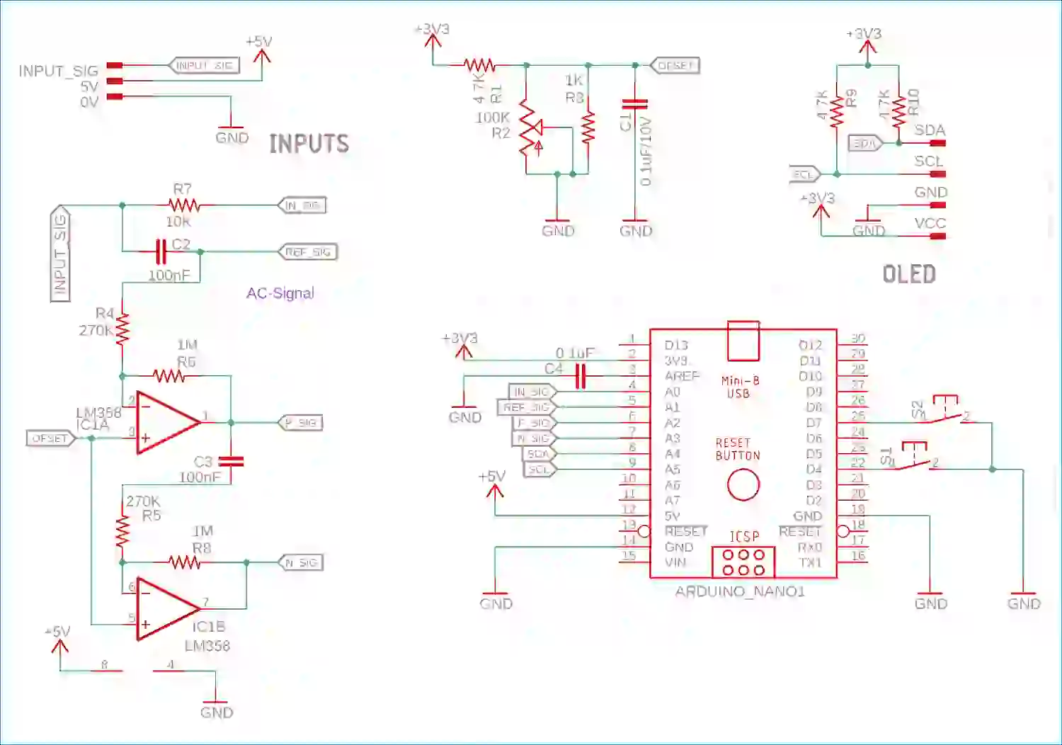
A parte principal do esquema usa um único circuito integrado de amplificador operacional, o LM358, que inclui dois amplificadores operacionais em um único chip. Como o sinal de entrada será CA e não temos uma construção de trilho dividido, há dois op-amps (de um único pacote Op-Amp de 8 pinos) usados para tornar o sinal acoplado a CA. Ambos os amplificadores operacionais são alimentados com uma tensão de referência que é usada para compensar o sinal e, usando entradas analógicas, é plotada no gráfico do osciloscópio. A compensação pode ser alterada usando o potenciômetro (que tem resistência de 100K). Ambos os amplificadores operacionais são configurados com o mesmo feedback negativo com uma configuração de ganho de x5.
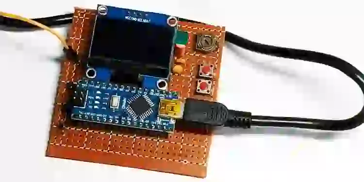
Além disso, o OLED está conectado sobre o A4 e o A5 é o pino I2C SCL e SDA com um resistor pull-up de 4,7K. Ele poderia funcionar com um simples conector USB. Os botões são usados para definir os parâmetros do osciloscópio. Construímos o circuito completo em cima de uma placa perfurada e, quando concluí minha configuração, ficou mais ou menos assim.
Osciloscópio Arduino – Explicação do código
A parte de codificação é complexa. Para entender como a codificação funciona, verifique os trechos de código abaixo.
Em primeiro lugar, a biblioteca para o Oscope é usada a partir da biblioteca SimpleSH1106.h de Peter Balch. É uma biblioteca muito rápida para o OLED que usa o chipset SH1106
As bibliotecas são definidas nas linhas abaixo.
#include <Wire.h>
#include <limits.h>
#include "SimpleSH1106.h"
#include <math.h>
As definições e os typedefs são definidos nas linhas abaixo –
ifndef getBit

#define getBit(sfr, bit) (_SFR_BYTE(sfr) & _BV(bit))

#endif
enum Tmode {DC5V, AC500mV, AC100mV, AC20mV,
               mLogic,
               mVoltmeter,
               maxMode1
               };
const Tmode maxMode = maxMode1 - 1;
Além disso, as constantes e as variáveis necessárias são declaradas a seguir –
/-----------------------------------------------------------------------------
// Global Constants
//-----------------------------------------------------------------------------
bool bHasLogic = true;
bool bHasFreq = true;
bool bHasVoltmeter = true;
bool bHasTestSignal = true;
bool bHasSigGen = false;
const long BAUDRATE  = 115200;  // Baud rate of UART in bps
const int COMMANDDELAY  = 10;  // ms to wait for the filling of Serial buffer
const int COMBUFFERSIZE = 4; // Size of buffer for incoming numbers
const int testSignalPin = 3;
const char ack = '@'; // acknowledge for comms command
const byte SampPerA = 5 + 6; // 6 nops
#define LoopNops __asm__("nop\n nop\n nop\n nop\n nop\n nop\n")
const int SampPerB = 20;
const int BtnHorz = 4; // pushbutton
const int BtnVert = 7; // pushbutton
const int FreeRunTimeout = 0x10; // 0.5 sec for free run
//-----------------------------------------------------------------------------
// Global Variables
//-----------------------------------------------------------------------------
Tmode curMode = DC5V;
uint8_t curVref = 1;
uint8_t curPeriod = 200;
uint8_t curPrescaler = 7;
char commandBuffer[COMBUFFERSIZE + 1];
bool TrigFalling = true;
uint8_t curSweep = 0;
byte yGraticulePage0, yGraticuleByte0, yGraticulePage1, yGraticuleByte1, yGraticulePage2, yGraticuleByte2;
byte* pxGratLabel;
byte* pyGratLabel;
byte xGratLabelLen, yGratLabelLen;
byte yGraticule0, yGraticule1, yGraticule2, xGraticule1, xGraticule2;
TmenuSel sel = sTime; // for main menu
byte adj[4] = {0, 0, 0, 0}; // for main menu
bool SendingSerial = false;
int curPwmMode = 0;
const int ADCBUFFERSIZE = 128;
uint8_t ADCBuffer[ADCBUFFERSIZE];
int ButtonsTimer1 = 0;
long Vin = 0; // used to display Voltmeter
As imagens do cardápio são declaradas aqui –
/-----------------------------------------------------------------------------
// images for the main menu
//-----------------------------------------------------------------------------
const byte imgMainMenuTop[] PROGMEM = {
  128, // width
  2, // pages
  1, 224, 147, 32, 130, 0, 3, 248, 252, 6, 130, 2, 3, 6, 252, 248, 130, 0, 2, 96, 240, 130, 144, 2, 176, 32, 130, 0, 2, 224, 240, 130,
  16, 3, 48, 32, 0, 130, 246, 130, 0, 130, 254, 130, 0, 130, 254, 130, 0, 2, 224, 240, 130, 16, 2, 240, 224, 130, 0, 2, 96, 240, 130,
  144, 2, 176, 32, 130, 0, 2, 224, 240, 130, 16, 5, 48, 32, 0, 224, 240, 130, 16, 2, 240, 224, 130, 0, 130, 240, 130, 16, 2, 240, 224,
  130, 0, 2, 224, 240, 130, 80, 2, 112, 96, 130, 0, 149, 32, 2, 224, 255, 149, 0, 3, 1, 3, 6, 130, 4, 3, 6, 3, 1, 130, 0, 2, 2, 6, 130,
  4, 2, 7, 3, 130, 0, 2, 3, 7, 130, 4, 3, 6, 2, 0, 130, 7, 130, 0, 130, 7, 130, 0, 130, 7, 130, 0, 2, 3, 7, 130, 4, 2, 7, 3, 130, 0, 2, 2, 6,
  130, 4, 2, 7, 3, 130, 0, 2, 3, 7, 130, 4, 5, 6, 2, 0, 3, 7, 130, 4, 2, 7, 3, 130, 0, 130, 63, 130, 4, 2, 7, 3, 130, 0, 2, 3, 7, 130, 4, 2,
  6, 2, 151, 0, 1, 255
};
const byte imgMainMenuMid[] PROGMEM = {
  128, // width
  1, // pages
  1, 255, 254, 0, 1, 255
};
const byte imgMainMenuBot[] PROGMEM = {
  128, // width
  1, // pages
  1, 255, 254, 128, 1, 255
};
const byte imgBoxTop[] PROGMEM = {
  128, // width
  1, // pages
  1, 248, 254, 8, 1, 248
};
const byte imgCaret1[] PROGMEM = {
  4, // width
  1, // pages
  4, 255, 126, 60, 24
};
const byte imgCaret2[] PROGMEM = {
  7, // width
  1, // pages
  7, 32, 48, 56, 60, 56, 48, 32
};
const byte imgTrian[] PROGMEM = {
  14, // width
  2, // pages
  28, 3,12,48,192,0,0,0,0,0,0,192,48,12,3,128,128,128,128,131,140,176,176,140,131,128,128,128,128};
const byte imgSine[] PROGMEM = {
  14, // width
  2, // pages
  28, 1,2,28,224,0,0,0,0,0,0,224,28,2,1,128,128,128,129,142,144,160,160,144,142,129,128,128,128};
const byte imgSquare[] PROGMEM = {
  14, // width
  2, // pages
  28, 0,0,0,255,1,1,1,1,1,1,255,0,0,0,160,160,160,191,128,128,128,128,128,128,191,160,160,160};
Os desenhos e linhas são declarados aqui –
//-----------------------------------------------------------------------------
// FillBar
//   fills the bits of a screen column from bit y1 to bit y2
//   makes a bar that must be part of 'page'
//   returns the bar
//-----------------------------------------------------------------------------
byte FillBar(byte y1, byte y2, byte page) {
  static byte lob[] = {0x00, 0x01, 0x03, 0x07, 0x0F, 0x1F, 0x3F, 0x7F, 0xFF};
  byte bar;
  if (page == y1 / 8) {
               if (page == y2 / 8)
               bar = lob[(y2 & 7) + 1];
               else
               bar = 0xFF;
               return bar - lob[y1 & 7];
  }
  else if (page == y2 / 8)
               return lob[(y2 & 7) + 1];
  else if ((page > y1 / 8) & (page < y2 / 8))
               return 0xFF;
  else
               return 0;
}
//-----------------------------------------------------------------------------
// draw box
//   draws a box around the screen with s written at top-left
//-----------------------------------------------------------------------------
void drawBox(char* s) {
  //           clearSH1106();
  DrawImageSH1106(0, 0, imgBoxTop);
  for (int i = 1; i < 7; i++)
               DrawImageSH1106(0, i, imgMainMenuMid);
  DrawImageSH1106(0, 7, imgMainMenuBot);
  DrawCharSH1106(' ',  6, 0, SmallFont);
  DrawStringSH1106(s,  7, 0, SmallFont);
}
//-----------------------------------------------------------------------------
// drawScreen
//   draws a graph like an oscilloscope
//   takes about 40mS
//-----------------------------------------------------------------------------
void drawScreen(void) {
  byte i, j, k, y, yPrev, bar, page, lastDrawn;
  byte* pxbz;
  byte* pybz;
  byte pxlenz, pylenz;
  switch (curMode) {
               case mVoltmeter:
               drawBox("Voltmeter");
               i = 20;
               if (Vin == LONG_MAX)
               DrawStringSH1106("++++",  i, 3, LargeDigitsFont);
               else if (Vin == -LONG_MAX)
               DrawStringSH1106("----",  i, 3, LargeDigitsFont);
               else {
               i += DrawIntDP2(Vin / 10,  i, 3, LargeDigitsFont);
               DrawStringSH1106("Volts",  i, 4, SmallFont);
               }
               return;
               case AC100mV:
               for ( i = 0; i < ADCBUFFERSIZE; i++ )
               ADCBuffer[i] = ADCBuffer[i] / 4;
               break;
               default:
               for ( i = 0; i < ADCBUFFERSIZE; i++ )
               ADCBuffer[i] = 63 - ADCBuffer[i] / 4;
  }
if ((curPeriod == 0) && (curMode <= AC20mV)) {
               yPrev = ADCBuffer[0];
               y = ADCBuffer[1];
               for ( i = 1; i < ADCBUFFERSIZE - 1; i++ ) {
               ADCBuffer[i] = (yPrev + y + ADCBuffer[i + 1]) / 3;
               yPrev = y;
               y = ADCBuffer[i + 1];
               }
  }
  pxbz = pxGratLabel;
  pxlenz = xGratLabelLen;
  pybz = pyGratLabel;
  pylenz = yGratLabelLen;
  for (page = 0; page <= 7; page++) {
               yPrev = ADCBuffer[0];
               lastDrawn = 255;
               setupPage(page);
               setupCol(0);
               Wire.beginTransmission(addr);
               Wire.write(0x40); // the following bytes are data
               for (i = 0; i < ADCBUFFERSIZE; i++) {
               if (i % 26 == 0) {
               Wire.endTransmission();
               Wire.beginTransmission(addr);
               Wire.write(0x40); // the following bytes are data
               }
               y = ADCBuffer[i];
               if (yPrev > y + 1) {
               if (yPrev == lastDrawn)
               yPrev--;
               bar = FillBar(y + 1, yPrev, page);
               lastDrawn = yPrev + 1;
               } else {
               bar = FillBar(yPrev, yPrev, page);
               lastDrawn = yPrev;
               }
               // }
               if ((page == 0) && (bar == 0x01) && (i & 1))
               bar = 0;
               if ((page == 7) && (bar == 0x80) && (i & 1))
               bar = 0;
               if (page == yGraticulePage0) {
               if (i & 8)
               bar = bar | yGraticuleByte0;
               }
               else if (page == yGraticulePage1) {
               if (i < pylenz)
               {
               bar |= *pybz;
               pybz++;
               }
               else if (i % 4 == 0)
               bar |= yGraticuleByte1;
               }
               else if (page == yGraticulePage2) {
               if (i % 4 == 0)
               bar |= yGraticuleByte2;
               }
               if ((i == xGraticule1) | (i == xGraticule2))
               bar = bar | 0x22;
               if ((page == 7) && (i > xGraticule2 - pxlenz - 2) && (i < xGraticule2 - 1)) {
               bar |= *pxbz;
               pxbz++;
               }
               Wire.write(bar);
               yPrev = y;
               }
               Wire.endTransmission();
  }
}
O ADC é declarado aqui –
//-----------------------------------------------------------------------------
// initADC()
//-----------------------------------------------------------------------------
void initADC(void) {
  if (curMode > AC20mV)
               return;
  ACSR = 0x10;
  ADCSRA = 0x97;
  ADCSRB = 0x0 ; //ADC Control and Status Register B
  // 0 Bit 6 – ACME: Analog Comparator Multiplexer Enable
  // 000 Bits 2:0 – ADTSn: ADC Auto Trigger Source [n = 2:0] Free Running mode
  ADMUX = 0x20 + (curVref << 6) + curMode; // ADC Multiplexer Selection Register
  // rr       Bits 7:6 – REFSn: Reference Selection = Vcc
  // 1        Bit 5 – ADLAR: ADC Left Adjust Result
  // aaaa  Bits 3:0 – MUXn: Analog Channel Selection
  DIDR0 = 0x3F; // Digital Input Disable Register 0
  // ADC0D=1, ADC1D=1, ADC2D=1, ADC3D=1, ADC4D=1, ADC5D=1, ADC6D=0, ADC7D=0
}
A varredura dos sinais na tela é declarada na figura abaixo
//-----------------------------------------------------------------------------
// setSweep
// set period and ADC prescaler
//-----------------------------------------------------------------------------
void setSweep(byte Sweep) {
  int x;
  long t;
  if (Sweep == 255) {
               if (curSweep == 0)
               curSweep = 6;
               else
               curSweep--;
  } else
               curSweep = Sweep;
  switch (curSweep) {
               case 0: curPeriod = 0;   curPrescaler = 2; t = 100;   pxGratLabel = &ax0_1[0]; xGratLabelLen = sizeof(ax0_1); break;
               case 1: curPeriod = 4;   curPrescaler = 2; t = 400;   pxGratLabel = &ax0_4[0]; xGratLabelLen = sizeof(ax0_4); break;
               case 2: curPeriod = 11;  curPrescaler = 3; t = 1000;  pxGratLabel = &ax1[0];   xGratLabelLen = sizeof(ax1);   break;
               case 3: curPeriod = 24;  curPrescaler = 3; t = 2000;  pxGratLabel = &ax2[0];   xGratLabelLen = sizeof(ax2);   break;
               case 4: curPeriod = 62;  curPrescaler = 4; t = 5000;  pxGratLabel = &ax5[0];   xGratLabelLen = sizeof(ax5);   break;
               case 5: curPeriod = 125; curPrescaler = 4; t = 10000; pxGratLabel = &ax10[0];  xGratLabelLen = sizeof(ax10);  break;
               case 6: curPeriod = 255; curPrescaler = 5; t = 20000; pxGratLabel = &ax20[0];  xGratLabelLen = sizeof(ax20);  break;

  }
  if (curSweep == 0)
               x = t;
  else
               x = 16 * t / (curPeriod * SampPerA + SampPerB);
  xGraticule1 = x / 2;
  xGraticule2 = x;
  SendAck();
}
//-----------------------------------------------------------------------------
// Sweep
//   sweeps siggen freq continuously
//   takes n mS for whole sweep
//   SDC regs are saved and restored
//   stops when receives a serial char
//-----------------------------------------------------------------------------
void Sweep(int n) {
  byte oldACSR = ACSR;
  byte oldADCSRA = ADCSRA;
  byte oldADCSRB = ADCSRB;
  byte oldADMUX = ADMUX;
  byte oldDIDR0 = DIDR0;
  byte oldDIDR1 = DIDR1;
  int fmin,fmax;
  fmin = calcFreq(freqSGLo);
  fmax = calcFreq(freqSGHi);
  int i=0;
  do {
               long f = exp((log(fmax) - log(fmin))*i/(n-1) + log(fmin)) +0.5;
               SG_freqSet(f, waveType);
               delay(1);
               i++;
               if (i >= n) i = 0;
  } while (!Serial.available());
  SG_freqSet(calcFreq(freqSGLo), waveType);
  ACSR = oldACSR;
  ADCSRA = oldADCSRA;
  ADCSRB = oldADCSRB;
  ADMUX = oldADMUX;
  DIDR0 = oldDIDR0;
  DIDR1 = oldDIDR1;
}
O incremento dos botões e a definição do modo são feitos da seguinte forma
//-----------------------------------------------------------------------------
// incMode
//   increment Mode
//   wrap around from max
//   skip over modes that are not allowed
//-----------------------------------------------------------------------------
int incMode(int mode) {
  mode++;
//if ((mode == mLogic)        && (!bHasLogic)) mode++;
//  if ((mode == mFreqLogic) && ((!bHasFreq) || (!bHasLogic))) mode++;
//  if ((mode == mFreqAC)   && (!bHasFreq)) mode++;
  if ((mode == mVoltmeter) && (!bHasVoltmeter)) mode++;
  if (mode > maxMode)
               return DC5V;
  else
               return mode;
}
//-----------------------------------------------------------------------------
// setMode
// set mode and Vref
//-----------------------------------------------------------------------------
void setMode(int mode) {
  int i;
  if (mode == 255) {
               curMode = incMode(curMode);
  } else
               curMode = mode;
  switch (curMode) {
               case DC5V:
               curVref = 1;
               i = (long)4000 * 64 / readVcc();
               if (i <= 63) {
               yGraticule1 = 63 - i;
               yGraticule2 = 63 - i / 2;
               yGraticule0 = 255;
               pyGratLabel = &ax4V[0];
               yGratLabelLen = sizeof(ax4V);
               } else {
               yGraticule2 = 63 - i;
               yGraticule1 = 63 - i / 2;
               yGraticule0 = 255;
               pyGratLabel = &ax2V[0];
               yGratLabelLen = sizeof(ax2V);
               }
               break;
               case AC500mV:
               curVref = 3;
               i = (byte)(0.5 / 1.1 * 256 / 4);
               yGraticule1 = 32 - i;
               yGraticule2 = 32 + i;
               yGraticule0 = 32;
               pyGratLabel = &ax0_5[0];
               yGratLabelLen = sizeof(ax0_5);
               break;
               case AC100mV:
               curVref = 3;
               i = (byte)(0.1 / 1.1 * (R1 + R2) / R2 * 256 / 4);
               yGraticule1 = 32 - i;
               yGraticule2 = 32 + i;
               yGraticule0 = 32;
               pyGratLabel = &ax0_1[0];
               yGratLabelLen = sizeof(ax0_1);
               break;
               case AC20mV:
               curVref = 3;
               i = (byte)(0.02 / 1.1 * (R1 + R2) / R2 * (R1 + R2) / R2 * 256 / 4);
               yGraticule1 = 32 - i;
               yGraticule2 = 32 + i;
               yGraticule0 = 32;
               pyGratLabel = &ax20[0];
               yGratLabelLen = sizeof(ax20);
               break;
               default:
               curVref = 1;
               yGraticule1 = 255;
               yGraticule2 = 255;
               yGraticule0 = 255;
               pyGratLabel = &ax20[0];
               yGratLabelLen = sizeof(ax20);
               break;
  }
O desenho do menu principal é feito usando os trechos de código abaixo
void drawMainMenu(void) {
  int ofs, x, yVcc, pg;
  switch (sel) {
               case sMode:         ofs = -1; break;
               case sTrigger: ofs = -2; break;
               case sTestSig: ofs = -5; break;
               case sSigGen:  ofs = bHasTestSignal ? -7 : -5; break;
               default:                 ofs = 0;
  }
  //  DrawImageSH1106(0,ofs,imgMainMenu);
  DrawImageSH1106(0, ofs + 0, imgMainMenuTop);
  for (x = 2; x < 14; x++)
               DrawImageSH1106(0, ofs + x, imgMainMenuMid);
  DrawImageSH1106(0, ofs + 10 + bHasTestSignal * 2 + bHasSigGen * 2, imgMainMenuBot);
  DrawImageSH1106(6, 3 + sel * 2 + ofs, imgCaret1);
  BoldSH1106 = true;
  pg = 3 + ofs;
  DrawStringSH1106("Time:",                                        12, pg, SmallFont); pg += 2;
  DrawStringSH1106((adj[1] <= AC20mV ? "Gain:" : "Mode:"), 12, pg, SmallFont); pg += 2;
  DrawStringSH1106("Trigger:",                                     12, pg, SmallFont); pg += 2;
  if (bHasTestSignal) {
               DrawStringSH1106("Test sig:",                      12, pg, SmallFont); pg += 2;
               if (bHasSigGen) {
               DrawStringSH1106("Signal Generator",                        12, pg, SmallFont); pg += 2;
               }
               DrawStringSH1106("Vcc:",                              12, pg, SmallFont); yVcc = pg; pg += 2;
  } else {
               if (bHasSigGen) {
               DrawStringSH1106("Vcc:",                              12, pg, SmallFont); yVcc = pg; pg += 2;
               DrawStringSH1106("Signal Generator",                        12, pg, SmallFont); pg += 2;
               } else {
               DrawStringSH1106("Vcc:",                              12, pg, SmallFont); yVcc = pg; pg += 2;
               }
  }
  BoldSH1106 = false;
  x = 62;
  pg = 3 + ofs;
  switch (adj[0]) {
               case 0:  DrawStringSH1106("1mS",   x, pg, SmallFont); break;
               case 1:  DrawStringSH1106("2mS",   x, pg, SmallFont); break;
               case 2:  DrawStringSH1106("5mS",   x, pg, SmallFont); break;
               case 3:  DrawStringSH1106("10mS",  x, pg, SmallFont); break;
               case 4:  DrawStringSH1106("20mS",  x, pg, SmallFont); break;
               case 5:  DrawStringSH1106("50mS",  x, pg, SmallFont); break;
               case 6:  DrawStringSH1106("100mS", x, pg, SmallFont); break;
  }
  pg += 2;
  switch (adj[1]) {
               case DC5V:          DrawStringSH1106("5V DC",            x, pg, SmallFont); break;
               case AC500mV:   DrawStringSH1106("0.5V AC",         x, pg, SmallFont); break;
               case AC100mV:   DrawStringSH1106("0.1V AC",         x, pg, SmallFont); break;
               case AC20mV:     DrawStringSH1106("20mV AC",       x, pg, SmallFont); break;
               //case mLogic:      DrawStringSH1106("Logic",              x, pg, SmallFont); break;
               //case mFreqLogic: DrawStringSH1106("Freq Logic", x, pg, SmallFont); break;
               //case mFreqAC:  DrawStringSH1106("Freq AC",         x, pg, SmallFont); break;
               case mVoltmeter: DrawStringSH1106("Voltmeter",  x, pg, SmallFont); break;
  }
  pg += 2;
 switch (adj[2]) {
               case 1:  DrawStringSH1106("Fall", x, pg, SmallFont); break;
               default: DrawStringSH1106("Rise", x, pg, SmallFont);
  }
  pg += 2;
  if (bHasTestSignal) {
               switch (adj[3]) {
               case 1:  DrawStringSH1106("31250Hz 32uS", x, pg, SmallFont); break;
               case 2:  DrawStringSH1106("3906Hz 256uS", x, pg, SmallFont); break;
               case 3:  DrawStringSH1106("977Hz 1024uS", x, pg, SmallFont); break;
               case 4:  DrawStringSH1106("488Hz 2048uS", x, pg, SmallFont); break;
               case 5:  DrawStringSH1106("244Hz 4096uS", x, pg, SmallFont); break;
               case 6:  DrawStringSH1106("122Hz 8192uS", x, pg, SmallFont); break;
               case 7:  DrawStringSH1106("31Hz 32768uS", x, pg, SmallFont); break;
               default: DrawStringSH1106("Off",                   x, pg, SmallFont);
               }
               pg += 2;
  }
  if (bHasSigGen)
               pg += 2;
  if (yVcc <= 7) {
               x += DrawIntDP2(readVcc() / 10, x, yVcc, SmallFont);
               DrawCharSH1106('V', x, yVcc, SmallFont);
  }
}
Os manipuladores de botões usados no – abaixo
void CheckButtons(void) {
  const byte timeout = 70; // 1 sec to show menu
  static int prevHorz = HIGH;
  static int prevVert = HIGH;
  int i;
  if (digitalRead(BtnHorz) == LOW) {
               if (prevHorz == HIGH) {
               switch (curMode) {
               //case mFreqLogic:
               // case mFreqAC:
               case mVoltmeter:
               ExecMenu();
               return;
               }
               ButtonsTimer1 = 0;
               myDelay(15);
               setSweep(255);
               prevHorz = LOW;
               } else {
               if (ButtonsTimer1 > timeout) {
               ExecMenu();
               return;
               }
               }
  } else {
               prevHorz = HIGH;
  }
  if (digitalRead(BtnVert) == LOW) {
               if (prevVert == HIGH) {
               ButtonsTimer1 = 0;
               myDelay(15);
               setMode(255);
               prevVert = LOW;
               } else {
               if (ButtonsTimer1 > timeout) {
               ExecMenu();
               return;
               }
               }
  } else {
               prevVert = HIGH;
  }
}
A medição da frequência é feita usando uma lógica de temporizador complexa na seguinte tabela
//=========================================================================
// Timer1 overflows every 65536 counts
//=========================================================================
ISR (TIMER1_OVF_vect)
{
  FC_overflowCount++;
}
//=========================================================================
// Timer1 Capture interrupt
//             invoked by comparator
//             read the current timer1 capture value
//             used in freq meter
//=========================================================================
ISR (TIMER1_CAPT_vect) {
  // grab counter value before it changes any more
  unsigned int timer1CounterValue = ICR1;  // see datasheet, page 117 (accessing 16-bit registers)
  unsigned long overflowCopy = FC_overflowCount;
  unsigned long t;
  static unsigned long prevT;
  // if just missed an overflow
  if ((TIFR1 & bit(TOV1)) && timer1CounterValue < 0x7FFF)
               overflowCopy++;
  t = (overflowCopy << 16) + timer1CounterValue;
  if ((!FC_firstAC) && (t-prevT > 100) && (t-prevT > FC_MaxPeriodAC))
               FC_MaxPeriodAC = t-prevT;
  prevT = t;
  FC_firstAC = false;
}
//=========================================================================
//  Timer0 Interrupt Service is invoked by hardware Timer0 every 1ms = 1000 Hz
//  used by frequancy counter
//  called every 1mS
//=========================================================================
ISR(TIMER0_COMPA_vect) {
  if (FC_Timeout >= FC_LogicPeriod) {           // end of gate time, measurement ready
               TCCR1B &= ~7;                  // Gate Off  / Counter T1 stopped
               bitClear(TIMSK0, OCIE0A);              // disable Timer0 Interrupt
               FC_OneSec = true;            // set global flag for end count period
               // calculate now frequeny value
               FC_freq = 0x10000 * FC_overflowCount; // mult #overflows by 65636
               FC_freq += TCNT1;            // add counter1 value
  }
  FC_Timeout++;                 // count number of interrupt events
  if (TIFR1 & 1) {                  // if Timer/Counter 1 overflow flag
               FC_overflowCount++;                       // count number of Counter1 overflows
               bitSet(TIFR1, TOV1);        // clear Timer/Counter 1 overflow flag
  }
}
//=========================================================================
// FC_InitLogic
//   count number of rising edges at D5 over mS period
//=========================================================================
void FC_InitLogic() {
  noInterrupts ();
  TIMSK0 = 0x00;
  delayMicroseconds(50);  // wait if any ints are pending
  FC_OneSec = false;                        // reset period measure flag
  FC_Timeout = 0;             // reset interrupt counter
  TCCR1A = 0x00; // timer output off
  TCCR1B = 0x07; // External clock source on T1 pin. Clock on rising edge.
  TCNT1 = 0x00; // counter = 0
  TCCR0A = 0x02; // compare output off; max count = OCRA
  TCCR0B = 0x03; // input clk is 16M/64
  TCNT0 = 0x16; // counter = 0 - why is this not 0? cos of set-up time?
  TIMSK0 = 0x00;
  OCR0A = 248; // max count value = CTC divider by 250 = 1mS
  GTCCR = 0x02; // reset prescaler
  FC_overflowCount = 0;
  bitSet(TIMSK0, OCIE0A);               // enable Timer0 Interrupt
  interrupts ();
}
//=========================================================================
// FC_InitAC
//   ACfreqAdcPin = 0..5 - use that ADC mux and measure period with Timer1
//=========================================================================
void FC_InitAC() {
  noInterrupts ();
  FC_disable();
  TCCR1A = 0; // reset Timer 1
  TCCR1B =  bit(CS10) | bit(ICES1);  // no prescaler, Input Capture Edge Select
  TIFR1 = bit(ICF1) | bit(TOV1);  // clear flags so we don't get a bogus interrupt
  TCNT1 = 0;        // Timer1 to zero
  FC_overflowCount = 0;  // for Timer1 overflows
  TIMSK1 = bit(TOIE1) | bit(ICIE1);   // interrupt on Timer 1 overflow and input capture
  ADCSRA = 0;
  DIDR1 = 1; // digital input of D6 is off
  ADMUX = ACfreqAdcPin;
  ACSR = bit(ACI)  | bit(ACIC) | (B10 << ACIS0); // "clear" interrupt flag; timer capture from comparator; falling edge
  ADCSRB = bit(ACME); // Comparator connected to ADC mux
  FC_firstAC = true;
  FC_Timeout = 0;
  FC_MaxPeriodAC = 0;
  interrupts ();
}
//=========================================================================
// FC_disable
//   turn off freq counter interrupts
//=========================================================================
void FC_disable() {
  TCCR0A = 0x03; // no compare output; Fast PWM up to 0xFF
  TCCR0B = 0x03; // no Output Compare; prescaler = 16MHz/64; overflow approx every 1mS
  TIMSK0 = 0x00; // Interrupt Mask Register = none
  GTCCR = 0x00; // Control Register = none
  OCR0A = 0x00; // Output Compare Register A = none
  OCR0B = 0x00; // Output Compare Register B = none
  TCCR1A = 0xC0;
  TCCR1B = 0x05;
  TCCR1C = 0x00;
  TIMSK1 = 0x00;
}
//=========================================================================
// FC_OneSecPassed
//   has 1 second passed?
//=========================================================================
bool FC_OneSecPassed() {
  static byte prevTimer1 = 0;
  byte i;
  static unsigned long t = 0;
  if (bitRead(TIFR0, TOV0)) // overflow every 1mS
               FC_Timeout++;
  bitSet(TIFR0, TOV0);
  return FC_Timeout > 1000;
}
//=========================================================================
// FC_CheckLogic
//   frequency measurer
//   call repeatedly
//   returns true when has timed out
//   result in FC_freq
//=========================================================================
bool FC_CheckLogic() {
  return FC_OneSec;
}
//=========================================================================
// FC_CheckAC
//   frequency measurer
//   call repeatedly
//   returns true when has timed out
//   result in FC_freq
//=========================================================================
bool FC_CheckAC() {
  unsigned long FC_elapsedTime;
  if (FC_OneSecPassed()) {
               if (FC_MaxPeriodAC > 0)
               FC_freq = 100 * F_CPU*1.004 / FC_MaxPeriodAC; // mult by 100 so can display 2 d.p.
               else
               FC_freq = 0;
               FC_InitAC();
               return true;
  }
  return false;
}
//-----------------------------------------------------------------------------
// myDelay
//   delays for approx mS milliSeconds
//   doesn't use any timers
//   doesn't affect interrupts
//-----------------------------------------------------------------------------
void myDelay(int mS) {
  for (int j = 0; j < mS; j++)
               delayMicroseconds(1000);
}
//-----------------------------------------------------------------------------
// MeasureVoltmeter
//   measures Voltmeter at Vin in mV
//   assumes resistors have been connected to pin:
//             Ra from pin to 5V
//             Rb from pin to 0V
//             Rc from pin to Vin
//----------------------------------------------------------------------------
Na configuração, o UART, o ADC e o OLED são iniciados, o buffer de memória é definido e o I2C é iniciado.
void setup (void) {
  // Open serial port with a baud rate of BAUDRATE b/s
  Serial.begin(baud rate);
  // Clear buffers
  memset( (void *)commandBuffer, 0, sizeof(commandBuffer) );
  // Activate interrupts
  sei();
  initADC();
  Serial.println("ArdOsc " __DATE__); // compilation date
  Serial.println("OK");
  setMode(0); // y-gain 5V
  setSweep(5);
  setPwmFrequency(testSignalPin, 3); // test signal 976Hz 1024uS
  pinMode(BtnHorz, INPUT_PULLUP);
  pinMode(BtnVert, INPUT_PULLUP);
  pinMode(LED_BUILTIN, OUTPUT);
  Wire.begin(); // join i2c bus as master
               TWBR = 1; // freq=888kHz period=1.125uS
  initSH1106();
}
No loop vazio, o loop depende do estado do interruptor em que modo ele está residindo, e o botão é pressionado para selecionar o modo.
//-----------------------------------------------------------------------------
// Main routines
// loop
//-----------------------------------------------------------------------------
void loop (void) {
  static int ButtonsTimer2 = 0;
  switch (curMode) {
               case mVoltmeter:
               if (CheckVoltmeter())
               drawScreen();
               break;
               default:
               if (!SendingSerial) {
               SendADC();
               switch (sweepType) {
               case sw20Frames: case sw100Frames: case sw500Frames:
               SG_StepSweep();
               }
               }
  }
  CheckButtons();
}
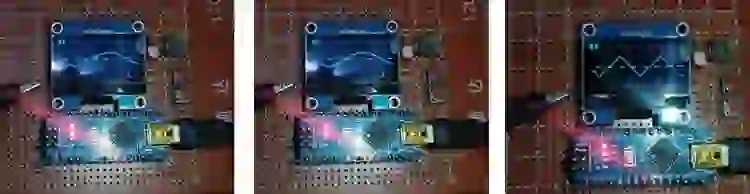
Funcionamento do osciloscópio Arduino
Todos os componentes são soldados na placa e alimentados com o cabo USB, e diferentes ondas são testadas na entrada.
A seguir estão as imagens de uma onda senoidal, uma onda quadrada e uma onda triangular.
Código completo do projeto
//-----------------------------------------------------------------------------
// Copyright 2018 Peter Balch
// subject to the GNU General Public License
//   displays samples on SH1106 screen as an oscilloscope
//-----------------------------------------------------------------------------
#include <Wire.h>
#include <limits.h>
#include "SimpleSH1106.h"
#include <math.h>
//-----------------------------------------------------------------------------
// Defines and Typedefs
//-----------------------------------------------------------------------------
// get register bit - faster: doesn't turn it into 0/1
#ifndef getBit
#define getBit(sfr, bit) (_SFR_BYTE(sfr) & _BV(bit))
#endif
enum Tmode {DC5V, AC500mV, AC100mV, AC20mV,
            mLogic,
            mVoltmeter,
            maxMode1
           };
const Tmode maxMode = maxMode1 - 1;
enum TmenuSel {sTime, sMode, sTrigger, sTestSig, sSigGen};
//-----------------------------------------------------------------------------
// Global Constants
//-----------------------------------------------------------------------------
bool bHasLogic = true;
bool bHasFreq = true;
bool bHasVoltmeter = true;
bool bHasTestSignal = true;
bool bHasSigGen = false;
const long BAUDRATE  = 115200;  // Baud rate of UART in bps
const int COMMANDDELAY  = 10;  // ms to wait for the filling of Serial buffer
const int COMBUFFERSIZE = 4; // Size of buffer for incoming numbers
const int testSignalPin = 3;
const char ack = '@'; // acknowledge for comms command
const byte SampPerA = 5 + 6; // 6 nops
#define LoopNops __asm__("nop\n nop\n nop\n nop\n nop\n nop\n")
const int SampPerB = 20;
const int BtnHorz = 4; // pushbutton
const int BtnVert = 7; // pushbutton
const int FreeRunTimeout = 0x10; // 0.5 sec for free run
//-----------------------------------------------------------------------------
// Global Variables
//-----------------------------------------------------------------------------
Tmode curMode = DC5V;
uint8_t curVref = 1;
uint8_t curPeriod = 200;
uint8_t curPrescaler = 7;
char commandBuffer[COMBUFFERSIZE + 1];
bool TrigFalling = true;
uint8_t curSweep = 0;
byte yGraticulePage0, yGraticuleByte0, yGraticulePage1, yGraticuleByte1, yGraticulePage2, yGraticuleByte2;
byte* pxGratLabel;
byte* pyGratLabel;
byte xGratLabelLen, yGratLabelLen;
byte yGraticule0, yGraticule1, yGraticule2, xGraticule1, xGraticule2;
TmenuSel sel = sTime; // for main menu
byte adj[4] = {0, 0, 0, 0}; // for main menu
bool SendingSerial = false;
int curPwmMode = 0;
const int ADCBUFFERSIZE = 128;
uint8_t ADCBuffer[ADCBUFFERSIZE];
int ButtonsTimer1 = 0;
long Vin = 0; // used to display Voltmeter
//-----------------------------------------------------------------------------
// globals used in SigGen
//-----------------------------------------------------------------------------
const byte numberOfDigits = 6; // number of digits in the frequency
byte freqSGLo[numberOfDigits] = {0, 0, 0, 1, 0, 0}; // 1000Hz SelSG = 0..numberOfDigits-1
byte freqSGHi[numberOfDigits] = {0, 0, 0, 0, 2, 0}; // 20kHz  SelSG = numberOfDigits..2*numberOfDigits-1
byte SelSG = numberOfDigits-1;
const byte SelSGSweep = 2*numberOfDigits;
const byte SelSGSine = 2*numberOfDigits+1;
const int wSine     = 0b0000000000000000;
const int wTriangle = 0b0000000000000010;
const int wSquare   = 0b0000000000101000;
enum TsweepType {swOff,sw20Frames,sw100Frames,sw500Frames,sw1Sec,sw5Sec,sw20Sec};
int waveType = wSine;
TsweepType sweepType = swOff;
const int SG_fsyncPin = 2;
const int SG_CLK = 13;
const int SG_DATA = 12;
int SG_iSweep,SG_nSweep;
//-----------------------------------------------------------------------------
// globals used in frequency counter
//-----------------------------------------------------------------------------
volatile boolean FC_OneSec;
volatile boolean FC_firstAC;
volatile unsigned long FC_overflowCount;
volatile unsigned long FC_MaxPeriodAC;
unsigned long FC_Timeout = 0;
unsigned long FC_freq;
const int ACfreqAdcPin = 3;
const int FC_LogicPeriod = 1006; // mS   slightly longer than 1 Sec for calibration
//-----------------------------------------------------------------------------
// labels for graticule
//-----------------------------------------------------------------------------
const int R1 = 100;
const int R2 = 27;
const byte ax2V[] = {98, 81, 73, 70, 0, 3, 28, 96, 28, 3};
const byte ax4V[] = {24, 22, 127, 16, 0, 3, 28, 96, 28, 3};
const byte ax0_1[] = {62, 65, 65, 62, 0, 64, 0, 2, 127 };
const byte ax0_2[] = {62, 65, 65, 62, 0, 64, 0, 98, 81, 73, 70 };
const byte ax0_4[] = {62, 65, 65, 62, 0, 64, 0, 24, 22, 127, 16 };
const byte ax0_5[] = {62, 65, 65, 62, 0, 64, 0, 47, 69, 69, 57};
const byte ax1[] = {2, 127 };
const byte ax2[] = {98, 81, 73, 70 };
const byte ax4[] = {24, 22, 127, 16 };
const byte ax5[] = {47, 69, 69, 57};
const byte ax10[] = {2, 127, 0, 62, 65, 65, 62 };
const byte ax20[] = {98, 81, 73, 70, 0, 62, 65, 65, 62 };
//-----------------------------------------------------------------------------
// images for main menu
//-----------------------------------------------------------------------------
const byte imgMainMenuTop[] PROGMEM = {
  128, // width
  2, // pages
  1, 224, 147, 32, 130, 0, 3, 248, 252, 6, 130, 2, 3, 6, 252, 248, 130, 0, 2, 96, 240, 130, 144, 2, 176, 32, 130, 0, 2, 224, 240, 130,
  16, 3, 48, 32, 0, 130, 246, 130, 0, 130, 254, 130, 0, 130, 254, 130, 0, 2, 224, 240, 130, 16, 2, 240, 224, 130, 0, 2, 96, 240, 130,
  144, 2, 176, 32, 130, 0, 2, 224, 240, 130, 16, 5, 48, 32, 0, 224, 240, 130, 16, 2, 240, 224, 130, 0, 130, 240, 130, 16, 2, 240, 224,
  130, 0, 2, 224, 240, 130, 80, 2, 112, 96, 130, 0, 149, 32, 2, 224, 255, 149, 0, 3, 1, 3, 6, 130, 4, 3, 6, 3, 1, 130, 0, 2, 2, 6, 130,
  4, 2, 7, 3, 130, 0, 2, 3, 7, 130, 4, 3, 6, 2, 0, 130, 7, 130, 0, 130, 7, 130, 0, 130, 7, 130, 0, 2, 3, 7, 130, 4, 2, 7, 3, 130, 0, 2, 2, 6,
  130, 4, 2, 7, 3, 130, 0, 2, 3, 7, 130, 4, 5, 6, 2, 0, 3, 7, 130, 4, 2, 7, 3, 130, 0, 130, 63, 130, 4, 2, 7, 3, 130, 0, 2, 3, 7, 130, 4, 2,
  6, 2, 151, 0, 1, 255
};
const byte imgMainMenuMid[] PROGMEM = {
  128, // width
  1, // pages
  1, 255, 254, 0, 1, 255
};
const byte imgMainMenuBot[] PROGMEM = {
  128, // width
  1, // pages
  1, 255, 254, 128, 1, 255
};
const byte imgBoxTop[] PROGMEM = {
  128, // width
  1, // pages
  1, 248, 254, 8, 1, 248
};
const byte imgCaret1[] PROGMEM = {
  4, // width
  1, // pages
  4, 255, 126, 60, 24
};
const byte imgCaret2[] PROGMEM = {
  7, // width
  1, // pages
  7, 32, 48, 56, 60, 56, 48, 32
};
const byte imgTrian[] PROGMEM = {
  14, // width
  2, // pages
  28, 3,12,48,192,0,0,0,0,0,0,192,48,12,3,128,128,128,128,131,140,176,176,140,131,128,128,128,128};
const byte imgSine[] PROGMEM = {
  14, // width
  2, // pages
  28, 1,2,28,224,0,0,0,0,0,0,224,28,2,1,128,128,128,129,142,144,160,160,144,142,129,128,128,128};
const byte imgSquare[] PROGMEM = {
  14, // width
  2, // pages
  28, 0,0,0,255,1,1,1,1,1,1,255,0,0,0,160,160,160,191,128,128,128,128,128,128,191,160,160,160};
//-----------------------------------------------------------------------------
// FillBar
//   fills the bits of a screen column from bit y1 to bit y2
//   makes a bar that must be part of 'page'
//   returns the bar
//-----------------------------------------------------------------------------
byte FillBar(byte y1, byte y2, byte page) {
  static byte lob[] = {0x00, 0x01, 0x03, 0x07, 0x0F, 0x1F, 0x3F, 0x7F, 0xFF};
  byte bar;
  if (page == y1 / 8) {
    if (page == y2 / 8)
      bar = lob[(y2 & 7) + 1];
    else
      bar = 0xFF;
    return bar - lob[y1 & 7];
  }
  else if (page == y2 / 8)
    return lob[(y2 & 7) + 1];
  else if ((page > y1 / 8) & (page < y2 / 8))
    return 0xFF;
  else
    return 0;
}
//-----------------------------------------------------------------------------
// drawBox
//   draws a box around the screen with s written aat top-left
//-----------------------------------------------------------------------------
void drawBox(char* s) {
  //      clearSH1106();
  DrawImageSH1106(0, 0, imgBoxTop);
  for (int i = 1; i < 7; i++)
    DrawImageSH1106(0, i, imgMainMenuMid);
  DrawImageSH1106(0, 7, imgMainMenuBot);
  DrawCharSH1106(' ',  6, 0, SmallFont);
  DrawStringSH1106(s,  7, 0, SmallFont);
}
//-----------------------------------------------------------------------------
// drawScreen
//   draws a graph like an oscilloscope
//   takes about 40mS
//-----------------------------------------------------------------------------
void drawScreen(void) {
  byte i, j, k, y, yPrev, bar, page, lastDrawn;
  byte* pxbz;
  byte* pybz;
  byte pxlenz, pylenz;
  switch (curMode) {
    case mVoltmeter:
      drawBox("Voltmeter");
      i = 20;
      if (Vin == LONG_MAX)
        DrawStringSH1106("++++",  i, 3, LargeDigitsFont);
      else if (Vin == -LONG_MAX)
        DrawStringSH1106("----",  i, 3, LargeDigitsFont);
      else {
        i += DrawIntDP2(Vin / 10,  i, 3, LargeDigitsFont);
        DrawStringSH1106("Volts",  i, 4, SmallFont);
      }
      return;
    case AC100mV:
      for ( i = 0; i < ADCBUFFERSIZE; i++ )
        ADCBuffer[i] = ADCBuffer[i] / 4;
      break;
    default:
      for ( i = 0; i < ADCBUFFERSIZE; i++ )
        ADCBuffer[i] = 63 - ADCBuffer[i] / 4;
  }
  if ((curPeriod == 0) && (curMode <= AC20mV)) {
    yPrev = ADCBuffer[0];
    y = ADCBuffer[1];
    for ( i = 1; i < ADCBUFFERSIZE - 1; i++ ) {
      ADCBuffer[i] = (yPrev + y + ADCBuffer[i + 1]) / 3;
      yPrev = y;
      y = ADCBuffer[i + 1];
    }
  }
  pxbz = pxGratLabel;
  pxlenz = xGratLabelLen;
  pybz = pyGratLabel;
  pylenz = yGratLabelLen;
  for (page = 0; page <= 7; page++) {
    yPrev = ADCBuffer[0];
    lastDrawn = 255;
    setupPage(page);
    setupCol(0);
    Wire.beginTransmission(addr);
    Wire.write(0x40); // the following bytes are data
    for (i = 0; i < ADCBUFFERSIZE; i++) {
      if (i % 26 == 0) {
        Wire.endTransmission();
        Wire.beginTransmission(addr);
        Wire.write(0x40); // the following bytes are data
      }
      y = ADCBuffer[i];
        if (yPrev > y + 1) {
          if (yPrev == lastDrawn)
            yPrev--;
          bar = FillBar(y + 1, yPrev, page);
          lastDrawn = yPrev + 1;
        } else {
          bar = FillBar(yPrev, yPrev, page);
          lastDrawn = yPrev;
        }
     // }
      if ((page == 0) && (bar == 0x01) && (i & 1))
        bar = 0;
      if ((page == 7) && (bar == 0x80) && (i & 1))
        bar = 0;
      if (page == yGraticulePage0) {
        if (i & 8)
          bar = bar | yGraticuleByte0;
      }
      else if (page == yGraticulePage1) {
        if (i < pylenz)
        {
          bar |= *pybz;
          pybz++;
        }
        else if (i % 4 == 0)
          bar |= yGraticuleByte1;
      }
      else if (page == yGraticulePage2) {
        if (i % 4 == 0)
          bar |= yGraticuleByte2;
      }
      if ((i == xGraticule1) | (i == xGraticule2))
        bar = bar | 0x22;
      if ((page == 7) && (i > xGraticule2 - pxlenz - 2) && (i < xGraticule2 - 1)) {
        bar |= *pxbz;
        pxbz++;
      }
      Wire.write(bar);
      yPrev = y;
    }
    Wire.endTransmission();
  }
}
//-----------------------------------------------------------------------------
// initADC()
//-----------------------------------------------------------------------------
void initADC(void) {
  if (curMode > AC20mV)
    return;
  ACSR = 0x10;
  ADCSRA = 0x97;
  ADCSRB = 0x0 ; //ADC Control and Status Register B
  // 0 Bit 6 – ACME: Analog Comparator Multiplexer Enable
  // 000 Bits 2:0 – ADTSn: ADC Auto Trigger Source [n = 2:0] Free Running mode
  ADMUX = 0x20 + (curVref << 6) + curMode; // ADC Multiplexer Selection Register
  // rr    Bits 7:6 – REFSn: Reference Selection = Vcc
  // 1     Bit 5 – ADLAR: ADC Left Adjust Result
  // aaaa  Bits 3:0 – MUXn: Analog Channel Selection
  DIDR0 = 0x3F; // Digital Input Disable Register 0
  // ADC0D=1, ADC1D=1, ADC2D=1, ADC3D=1, ADC4D=1, ADC5D=1, ADC6D=0, ADC7D=0
}
//-----------------------------------------------------------------------------
// printStatus
//   print various register values
//-----------------------------------------------------------------------------
//-----------------------------------------------------------------------------
// setPwmFrequency
//        timer  mode=1     mode=2     mode=3      mode=4       mode=5        mode=6       mode=7
// pin=5    0    f=62500/1  f=62500/8  f=62500/64  f=62500/256  f=62500/1024
// pin=6    0    f=62500/1  f=62500/8  f=62500/64  f=62500/256  f=62500/1024
// pin=9    1    f=31250/1  f=31250/8  f=31250/64  f=31250/256  f=31250/1024
// pin=10   1    f=31250/1  f=31250/8  f=31250/64  f=31250/256  f=31250/1024
// pin=3    2    f=31250/1  f=31250/8  f=31250/32  f=31250/64   f=31250/128   f=31250/256  f=31250/1024
// pin=11   2    f=31250/1  f=31250/8  f=31250/32  f=31250/64   f=31250/128   f=31250/256  f=31250/1024
//-----------------------------------------------------------------------------
void setPwmFrequency(int pin, byte mode) {
  SendAck();
  curPwmMode = mode;
  if (mode == 0) {
    analogWrite(pin, 0);
  } else {
    analogWrite(pin, 128);
    if (pin == 5 || pin == 6 || pin == 9 || pin == 10) {
      if (pin == 5 || pin == 6) {
        TCCR0B = TCCR0B & 0b11111000 | mode;
      } else {
        TCCR1B = TCCR1B & 0b11111000 | mode;
      }
    } else if (pin == 3 || pin == 11) {
      TCCR2B = TCCR2B & 0b11111000 | mode;
    }
  }
}
//-----------------------------------------------------------------------------
// StartTimer1
// TIFR1 becomes non-zero after
//    overflow*1024/16000000 sec
//-----------------------------------------------------------------------------
void StartTimer1(word overflow) {
  TCCR1A = 0xC0; // Set OC1A on Compare Match
  TCCR1B = 0x05; // prescaler = 1024
  TCCR1C = 0x00; // no pwm output
  OCR1AH = highByte(overflow);
  OCR1AL = lowByte(overflow);
  OCR1BH = 0;
  OCR1BL = 0;
  TIMSK1 = 0x00; // no interrupts
  TCNT1H = 0; // must be written first
  TCNT1L = 0; // clear the counter
  TIFR1 = 0xFF; // clear all flags
}
//-----------------------------------------------------------------------------
// SendAck
//   if sending serial then send @
//-----------------------------------------------------------------------------
void SendAck(void) {
  if (SendingSerial)
    Serial.print(ack);
}
//-----------------------------------------------------------------------------
// readVcc
//    result in mV
//-----------------------------------------------------------------------------
long readVcc(void) {
  long result;
  ACSR = 0x10;
  ADCSRA = 0x97;
  ADCSRB = 0x0;
  // Read 1.1V reference against AVcc
  ADMUX = _BV(REFS0) | _BV(MUX3) | _BV(MUX2) | _BV(MUX1);
  myDelay(2);
  ADCSRA |= _BV(ADSC); // Convert
  while (bit_is_set(ADCSRA, ADSC));
  result = ADCL;
  result |= ADCH << 8;
  result = 1125300L / result; // Back-calculate AVcc in mV
  initADC(); // to set up for next sweep
  return result;
}
void GetADCSamples(void) {
  uint8_t d;
  uint8_t* p;
  const int hysteresis = 2;
  bool Trig;
  Trig = TrigFalling ^ (curMode != AC100mV);
  initADC();
  ADCSRA = 0x80 + (curPrescaler & 7); // ADC Control and Status Register A
  // 1   Bit 7 – ADEN: ADC Enable
  // 0   Bit 6 – ADSC: ADC Start Conversion
  // 0   Bit 5 – ADATE: ADC Auto Trigger Enable
  // 0   Bit 4 – ADIF: ADC Interrupt Flag
  // 0   Bit 3 – ADIE: ADC Interrupt Enable
  // nnn Bits 2:0 – ADPSn: ADC Prescaler Select [n = 2:0]
  StartTimer1(0); // no timeout
  for (d = 0; d < 10; d++ ) { // make sure ADC is running
    bitSet(ADCSRA, ADSC); // start ADC conversion
    while (!getBit(ADCSRA, ADIF)) ; // wait for ADC
    bitSet(ADCSRA, ADIF); // clear the flag
  }
  if (curPeriod == 0) { // 1Msps
    while (Trig ? (ADCH >= 0x80 - hysteresis) : (ADCH < 0x80 + hysteresis)) {
      d = TCNT1L; // to force read of TCNT1H
      if (TCNT1H > FreeRunTimeout) goto freeRunFast;
      bitSet(ADCSRA, ADSC);
    }
    while (Trig ? (ADCH < 0x80 + hysteresis) : (ADCH >= 0x80 - hysteresis)) {
      d = TCNT1L; // to force read of TCNT1H
      if (TCNT1H > FreeRunTimeout) goto freeRunFast;
      bitSet(ADCSRA, ADSC);
    }
freeRunFast:
    for (p = ADCBuffer; p < ADCBuffer + ADCBUFFERSIZE; p++ ) {
      *p = ADCH;
      __asm__("nop"); // pad it to 16 instructions
      __asm__("nop"); // pad it to 16 instructions
      bitSet(ADCSRA, ADSC);
    }
  } else { // slower than 1Msps
    do { // wait for comparator low
      bitSet(ADCSRA, ADSC); // start ADC conversion
      for (d = 0; d < curPeriod; d++ )
        LoopNops;
      d = TCNT1L; // to force read of TCNT1H
      if (TCNT1H > FreeRunTimeout) goto freeRunSlow;
    } while (Trig ? (ADCH >= 0x80 - hysteresis) : (ADCH < 0x80 + hysteresis));
    do { // wait for comparator high
      bitSet(ADCSRA, ADSC); // start ADC conversion
      for (d = 0; d < curPeriod; d++ )
        LoopNops;
      d = TCNT1L; // to force read of TCNT1H
      if (TCNT1H > FreeRunTimeout) goto freeRunSlow;
    } while (Trig ? (ADCH < 0x80 + hysteresis) : (ADCH >= 0x80 - hysteresis));
freeRunSlow:
    bitSet(ADCSRA, ADSC); // start ADC conversion
    for ( p = ADCBuffer; p < ADCBuffer + ADCBUFFERSIZE; p++ ) {
      for (d = 0; d < curPeriod; d++ )
        LoopNops;
      *p = ADCH;
      bitSet(ADCSRA, ADSC); // start ADC conversion
    }
  }
}
//-----------------------------------------------------------------------------
// SendADC
//   uses curPrescaler,curPeriod,curMode,curVref
//
//   read and Tx a buffer-full of samples
//   prescaler
//     7 128
//     6 64
//     5 32
//     4 16
//     3 8
//     2 4
//     1 2
//     0 2
//   period: sample period
//     0:  16 clocks
//     n:  n*SampPerA+SampPerB clocks
//-----------------------------------------------------------------------------
void SendADC() {
  memset( (void *)ADCBuffer, 0, sizeof(ADCBuffer) );
  noInterrupts();
//  if (curMode == mLogic)
//    GetLogicSamples();
//  else
GetADCSamples();
  interrupts();
  digitalWrite(LED_BUILTIN, HIGH);
  if (SendingSerial) {
    Serial.write((uint8_t)0xAA);
    Serial.write((uint8_t)0xBB);
    Serial.write((uint8_t)0xCC);
    Serial.write((uint8_t *)ADCBuffer, ADCBUFFERSIZE);
  }
  drawScreen();
  digitalWrite(LED_BUILTIN, LOW);
  int t = TCNT1L; // to force read of TCNT1H
  ButtonsTimer1 += TCNT1H;
}
//-----------------------------------------------------------------------------
// setSweep
// set period and ADC prescaler
//-----------------------------------------------------------------------------
void setSweep(byte Sweep) {
  int x;
  long t;
  if (Sweep == 255) {
    if (curSweep == 0)
      curSweep = 6;
    else
      curSweep--;
  } else
    curSweep = Sweep;
  switch (curSweep) {
    case 0: curPeriod = 0;   curPrescaler = 2; t = 100;   pxGratLabel = &ax0_1[0]; xGratLabelLen = sizeof(ax0_1); break;
    case 1: curPeriod = 4;   curPrescaler = 2; t = 400;   pxGratLabel = &ax0_4[0]; xGratLabelLen = sizeof(ax0_4); break;
    case 2: curPeriod = 11;  curPrescaler = 3; t = 1000;  pxGratLabel = &ax1[0];   xGratLabelLen = sizeof(ax1);   break;
    case 3: curPeriod = 24;  curPrescaler = 3; t = 2000;  pxGratLabel = &ax2[0];   xGratLabelLen = sizeof(ax2);   break;
    case 4: curPeriod = 62;  curPrescaler = 4; t = 5000;  pxGratLabel = &ax5[0];   xGratLabelLen = sizeof(ax5);   break;
    case 5: curPeriod = 125; curPrescaler = 4; t = 10000; pxGratLabel = &ax10[0];  xGratLabelLen = sizeof(ax10);  break;
    case 6: curPeriod = 255; curPrescaler = 5; t = 20000; pxGratLabel = &ax20[0];  xGratLabelLen = sizeof(ax20);  break;
  }
  if (curSweep == 0)
    x = t;
  else
    x = 16 * t / (curPeriod * SampPerA + SampPerB);
  xGraticule1 = x / 2;
  xGraticule2 = x;
  SendAck();
}
//-----------------------------------------------------------------------------
// incMode
//   increment Mode
//   wrap around from max
//   skip over modes that are not allowed
//-----------------------------------------------------------------------------
int incMode(int mode) {
  mode++;
//if ((mode == mLogic)     && (!bHasLogic)) mode++;
//  if ((mode == mFreqLogic) && ((!bHasFreq) || (!bHasLogic))) mode++;
//  if ((mode == mFreqAC)    && (!bHasFreq)) mode++;
  if ((mode == mVoltmeter) && (!bHasVoltmeter)) mode++;
  if (mode > maxMode)
    return DC5V;
  else
    return mode;
}
//-----------------------------------------------------------------------------
// setMode
// set mode and Vref
//-----------------------------------------------------------------------------
void setMode(int mode) {
  int i;
  if (mode == 255) {
    curMode = incMode(curMode);
  } else
    curMode = mode;
  switch (curMode) {
    case DC5V:
      curVref = 1;
      i = (long)4000 * 64 / readVcc();
      if (i <= 63) {
        yGraticule1 = 63 - i;
        yGraticule2 = 63 - i / 2;
        yGraticule0 = 255;
        pyGratLabel = &ax4V[0];
        yGratLabelLen = sizeof(ax4V);
      } else {
        yGraticule2 = 63 - i;
        yGraticule1 = 63 - i / 2;
        yGraticule0 = 255;
        pyGratLabel = &ax2V[0];
        yGratLabelLen = sizeof(ax2V);
      }
      break;
    case AC500mV:
      curVref = 3;
      i = (byte)(0.5 / 1.1 * 256 / 4);
      yGraticule1 = 32 - i;
      yGraticule2 = 32 + i;
      yGraticule0 = 32;
      pyGratLabel = &ax0_5[0];
      yGratLabelLen = sizeof(ax0_5);
      break;
    case AC100mV:
      curVref = 3;
      i = (byte)(0.1 / 1.1 * (R1 + R2) / R2 * 256 / 4);
      yGraticule1 = 32 - i;
      yGraticule2 = 32 + i;
      yGraticule0 = 32;
      pyGratLabel = &ax0_1[0];
      yGratLabelLen = sizeof(ax0_1);
      break;
    case AC20mV:
      curVref = 3;
      i = (byte)(0.02 / 1.1 * (R1 + R2) / R2 * (R1 + R2) / R2 * 256 / 4);
      yGraticule1 = 32 - i;
      yGraticule2 = 32 + i;
      yGraticule0 = 32;
      pyGratLabel = &ax20[0];
      yGratLabelLen = sizeof(ax20);
      break;
    default:
      curVref = 1;
      yGraticule1 = 255;
      yGraticule2 = 255;
      yGraticule0 = 255;
      pyGratLabel = &ax20[0];
      yGratLabelLen = sizeof(ax20);
      break;
  }
  switch (curMode) {
    case mVoltmeter:
      Vin = 0;
      drawScreen();
      break;
    default: FC_disable();
  }
  yGraticulePage0 = yGraticule0 / 8;
  yGraticuleByte0 = 1 << (yGraticule0 % 8);
  yGraticulePage1 = yGraticule1 / 8;
  yGraticuleByte1 = 1 << (yGraticule1 % 8);
  yGraticulePage2 = yGraticule2 / 8;
  yGraticuleByte2 = 1 << (yGraticule2 % 8);
  SendAck();
}
//-----------------------------------------------------------------------------
// drawMainMenu
//   draw the main menu for values of sel and adj
//-----------------------------------------------------------------------------
void drawMainMenu(void) {
  int ofs, x, yVcc, pg;
  switch (sel) {
    case sMode:    ofs = -1; break;
    case sTrigger: ofs = -2; break;
    case sTestSig: ofs = -5; break;
    case sSigGen:  ofs = bHasTestSignal ? -7 : -5; break;
    default:       ofs = 0;
  }
  //  DrawImageSH1106(0,ofs,imgMainMenu);
  DrawImageSH1106(0, ofs + 0, imgMainMenuTop);
  for (x = 2; x < 14; x++)
    DrawImageSH1106(0, ofs + x, imgMainMenuMid);
  DrawImageSH1106(0, ofs + 10 + bHasTestSignal * 2 + bHasSigGen * 2, imgMainMenuBot);
  DrawImageSH1106(6, 3 + sel * 2 + ofs, imgCaret1);
  BoldSH1106 = true;
  pg = 3 + ofs;
  DrawStringSH1106("Time:",                                12, pg, SmallFont); pg += 2;
  DrawStringSH1106((adj[1] <= AC20mV ? "Gain:" : "Mode:"), 12, pg, SmallFont); pg += 2;
  DrawStringSH1106("Trigger:",                             12, pg, SmallFont); pg += 2;
  if (bHasTestSignal) {
    DrawStringSH1106("Test sig:",                          12, pg, SmallFont); pg += 2;
    if (bHasSigGen) {
      DrawStringSH1106("Signal Generator",                 12, pg, SmallFont); pg += 2;
    }
    DrawStringSH1106("Vcc:",                               12, pg, SmallFont); yVcc = pg; pg += 2;
  } else {
    if (bHasSigGen) {
      DrawStringSH1106("Vcc:",                             12, pg, SmallFont); yVcc = pg; pg += 2;
      DrawStringSH1106("Signal Generator",                 12, pg, SmallFont); pg += 2;
    } else {
      DrawStringSH1106("Vcc:",                             12, pg, SmallFont); yVcc = pg; pg += 2;
    }
  }
  BoldSH1106 = false;
  x = 62;
  pg = 3 + ofs;
  switch (adj[0]) {
    case 0:  DrawStringSH1106("1mS",   x, pg, SmallFont); break;
    case 1:  DrawStringSH1106("2mS",   x, pg, SmallFont); break;
    case 2:  DrawStringSH1106("5mS",   x, pg, SmallFont); break;
    case 3:  DrawStringSH1106("10mS",  x, pg, SmallFont); break;
    case 4:  DrawStringSH1106("20mS",  x, pg, SmallFont); break;
    case 5:  DrawStringSH1106("50mS",  x, pg, SmallFont); break;
    case 6:  DrawStringSH1106("100mS", x, pg, SmallFont); break;
  }
  pg += 2;
  switch (adj[1]) {
    case DC5V:       DrawStringSH1106("5V DC",      x, pg, SmallFont); break;
    case AC500mV:    DrawStringSH1106("0.5V AC",    x, pg, SmallFont); break;
    case AC100mV:    DrawStringSH1106("0.1V AC",    x, pg, SmallFont); break;
    case AC20mV:     DrawStringSH1106("20mV AC",    x, pg, SmallFont); break;
    //case mLogic:     DrawStringSH1106("Logic",      x, pg, SmallFont); break;
    //case mFreqLogic: DrawStringSH1106("Freq Logic", x, pg, SmallFont); break;
    //case mFreqAC:    DrawStringSH1106("Freq AC",    x, pg, SmallFont); break;
    case mVoltmeter: DrawStringSH1106("Voltmeter",  x, pg, SmallFont); break;
  }
  pg += 2;
  switch (adj[2]) {
    case 1:  DrawStringSH1106("Fall", x, pg, SmallFont); break;
    default: DrawStringSH1106("Rise", x, pg, SmallFont);
  }
  pg += 2;
  if (bHasTestSignal) {
    switch (adj[3]) {
      case 1:  DrawStringSH1106("31250Hz 32uS", x, pg, SmallFont); break;
      case 2:  DrawStringSH1106("3906Hz 256uS", x, pg, SmallFont); break;
      case 3:  DrawStringSH1106("977Hz 1024uS", x, pg, SmallFont); break;
      case 4:  DrawStringSH1106("488Hz 2048uS", x, pg, SmallFont); break;
      case 5:  DrawStringSH1106("244Hz 4096uS", x, pg, SmallFont); break;
      case 6:  DrawStringSH1106("122Hz 8192uS", x, pg, SmallFont); break;
      case 7:  DrawStringSH1106("31Hz 32768uS", x, pg, SmallFont); break;
      default: DrawStringSH1106("Off",          x, pg, SmallFont);
    }
    pg += 2;
  }
  if (bHasSigGen)
    pg += 2;
  if (yVcc <= 7) {
    x += DrawIntDP2(readVcc() / 10, x, yVcc, SmallFont);
    DrawCharSH1106('V', x, yVcc, SmallFont);
  }
}
//-----------------------------------------------------------------------------
// incAdj
//   increment the value of adj
//-----------------------------------------------------------------------------
void incAdj(void) {
  if (sel == sSigGen)
    return;
  if (sel == sMode) {
    adj[1] = incMode(adj[1]);
  } else {
    adj[sel]++;
    if (adj[0] > 6) adj[0] = 0;
    if (adj[2] > 1) adj[2] = 0;
    if (adj[3] > 7) adj[3] = 0;
  }
  drawMainMenu;
}
//-----------------------------------------------------------------------------
// incSel
//   increment the value of sel
//-----------------------------------------------------------------------------
void incSel(void) {
  if (bHasTestSignal) {
    if (bHasSigGen) {
      if (sel == sSigGen)
        sel = sTime - 1;
    } else {
      if (sel == sTestSig)
        sel = sTime - 1;
    }
  } else {
    if (bHasSigGen) {
      if (sel == sSigGen)
        sel = sTime - 1;
      if (sel == sTrigger)
        sel = sSigGen - 1;
    } else {
      if (sel == sTrigger)
        sel = sTime - 1;
    }
  }
  sel = sel + 1;
  drawMainMenu;
}
//-----------------------------------------------------------------------------
// DrawIntDP2
//   draws the int 1234 with format 12.34
//   at x,page
//   returns width drawn
//-----------------------------------------------------------------------------
int DrawIntDP2(int i, byte x, byte page, word Font) {
  int start;
  start = x;
  if (i < 0) {
    i = -i;
    x += DrawCharSH1106('-', x, page, Font);
  }
  x += DrawIntSH1106(i / 100, x, page, Font);
  x += DrawCharSH1106('.', x, page, Font);
  x += DrawIntSH1106((i / 10) % 10, x, page, Font);
  x += DrawIntSH1106(i % 10, x, page, Font);
  return x - start;
}
//-----------------------------------------------------------------------------
// drawSigGenMenu
//-----------------------------------------------------------------------------
void drawSigGenMenu(void) {
  byte x,y,i;
  drawBox("Signal Generator");
  if (sweepType == swOff) {
    x = 20;
    y = 3;
    for (i = numberOfDigits - 1; i < numberOfDigits; i--) {
      if (i == SelSG)
        DrawImageSH1106(x+2, y+2, imgCaret2);
      x += DrawIntSH1106(freqSGLo[i],  x, y, LargeDigitsFont);
    }
  } else {
    x = 60;
    y = 2;
    DrawStringSH1106("Max Freq:",     12, y, SmallFont);
    for (i = numberOfDigits - 1; i < numberOfDigits; i--) {
      if (i == SelSG-numberOfDigits)
        DrawImageSH1106(x-2, y+1, imgCaret2);
      x += DrawIntSH1106(freqSGHi[i],  x, y, SmallFont);
    }
    DrawStringSH1106(" Hz",  x, y, SmallFont);
    x = 60;
    y = 4;
    DrawStringSH1106("Min Freq:",     12, y, SmallFont);
    for (i = numberOfDigits - 1; i < numberOfDigits; i--) {
      if (i == SelSG)
        DrawImageSH1106(x-2, y+1, imgCaret2);
      x += DrawIntSH1106(freqSGLo[i],  x, y, SmallFont);
    }
    DrawStringSH1106(" Hz",  x, y, SmallFont);
  }
  x = 12;
  y = 6;
  if (SelSG == SelSGSine)
    DrawImageSH1106(x-6, y, imgCaret1);
//  switch (waveType) {
//    case wSine:      DrawStringSH1106("Sine",     x, y, SmallFont); break;
//    case wTriangle:  DrawStringSH1106("Triangle", x, y, SmallFont); break;
//    case wSquare:    DrawStringSH1106("Square",   x, y, SmallFont); break;
//  }
  for (x=12;x<40;x+=14)
  switch (waveType) {
    case wSine:      DrawImageSH1106(x, y, imgSine); break;
    case wTriangle:  DrawImageSH1106(x, y, imgTrian); break;
    case wSquare:    DrawImageSH1106(x, y, imgSquare); break;
  }
  x = 54;
  y = 6;
  switch (sweepType) {
    case swOff:       DrawStringSH1106("Constant",       x, y, SmallFont); break;
    case sw1Sec:      DrawStringSH1106("Sweep 1 Sec",    x, y, SmallFont); break;
    case sw5Sec:      DrawStringSH1106("Sweep 5 Sec",    x, y, SmallFont); break;
    case sw20Sec:     DrawStringSH1106("Sweep 20 Sec",   x, y, SmallFont); break;
    case sw20Frames:  DrawStringSH1106("Swp 20 frames",  x, y, SmallFont); break;
    case sw100Frames: DrawStringSH1106("Swp 100 frames", x, y, SmallFont); break;
    case sw500Frames: DrawStringSH1106("Swp 500 frames", x, y, SmallFont); break;
  }
  if (SelSG == SelSGSweep)
    DrawImageSH1106(x-6, y, imgCaret1);
}
//-----------------------------------------------------------------------------
//returns 10^y
//-----------------------------------------------------------------------------
unsigned long Power(int y) {
  unsigned long t = 1;
  for (byte i = 0; i < y; i++)
    t = t * 10;
  return t;
}
//-----------------------------------------------------------------------------
//calculate the frequency from the array.
//-----------------------------------------------------------------------------
unsigned long calcFreq(byte* freqSG) {
  unsigned long i = 0;
  for (byte x = 0; x < numberOfDigits; x++)
    i = i + freqSG[x] * Power(x);
  return i;
}
//-----------------------------------------------------------------------------
// SG_WriteRegister
//-----------------------------------------------------------------------------
void SG_WriteRegister(word dat) {
  digitalWrite(SG_CLK, LOW);
  digitalWrite(SG_CLK, HIGH);
  digitalWrite(SG_fsyncPin, LOW);
  for (byte i = 0; i < 16; i++) {
    if (dat & 0x8000)
      digitalWrite(SG_DATA, HIGH);
    else
      digitalWrite(SG_DATA, LOW);
    dat = dat << 1;
    digitalWrite(SG_CLK, HIGH);
    digitalWrite(SG_CLK, LOW);
  }
  digitalWrite(SG_CLK, HIGH);
  digitalWrite(SG_fsyncPin, HIGH);
}
//-----------------------------------------------------------------------------
// SG_Reset
//-----------------------------------------------------------------------------
void SG_Reset() {
  delay(100);
  SG_WriteRegister(0x100);
  delay(100);
}
//-----------------------------------------------------------------------------
// SG_freqReset
//    reset the SG regs then set the frequency and wave type
//-----------------------------------------------------------------------------
void SG_freqReset(long frequency, int wave) {
  long fl = frequency * (0x10000000 / 25000000.0);
  SG_WriteRegister(0x2100);
  SG_WriteRegister((int)(fl & 0x3FFF) | 0x4000);
  SG_WriteRegister((int)((fl & 0xFFFC000) >> 14) | 0x4000);
  SG_WriteRegister(0xC000);
  SG_WriteRegister(wave);
  waveType = wave;
}
//-----------------------------------------------------------------------------
// SG_freqSet
//    set the SG frequency regs
//-----------------------------------------------------------------------------
void SG_freqSet(long frequency, int wave) {
  long fl = frequency * (0x10000000 / 25000000.0);
  SG_WriteRegister(0x2000 | wave);
  SG_WriteRegister((int)(fl & 0x3FFF) | 0x4000);
  SG_WriteRegister((int)((fl & 0xFFFC000) >> 14) | 0x4000);
}
//-----------------------------------------------------------------------------
// SG_StepSweep
//    increment the FG frequency
//-----------------------------------------------------------------------------
void SG_StepSweep(void) {
  if (SG_iSweep > SG_nSweep) SG_iSweep = 0;
  long f = exp((log(calcFreq(freqSGHi)) - log(calcFreq(freqSGLo)))*SG_iSweep/SG_nSweep + log(calcFreq(freqSGLo))) +0.5;
  SG_freqSet(f, waveType);
  SG_iSweep++;
}
//-----------------------------------------------------------------------------
// Sweep
//   sweeps siggen freq continuously
//   takes n mS for whole sweep
//   SDC regs are saved and restored
//   stops when receives a serial char
//-----------------------------------------------------------------------------
void Sweep(int n) {
  byte oldACSR = ACSR;
  byte oldADCSRA = ADCSRA;
  byte oldADCSRB = ADCSRB;
  byte oldADMUX = ADMUX;
  byte oldDIDR0 = DIDR0;
  byte oldDIDR1 = DIDR1;
  int fmin,fmax;
  fmin = calcFreq(freqSGLo);
  fmax = calcFreq(freqSGHi);
  int i=0;
  do {
    long f = exp((log(fmax) - log(fmin))*i/(n-1) + log(fmin)) +0.5;
    SG_freqSet(f, waveType);
    delay(1);
    i++;
    if (i >= n) i = 0;
  } while (!Serial.available());
  SG_freqSet(calcFreq(freqSGLo), waveType);
  ACSR = oldACSR;
  ADCSRA = oldADCSRA;
  ADCSRB = oldADCSRB;
  ADMUX = oldADMUX;
  DIDR0 = oldDIDR0;
  DIDR1 = oldDIDR1;
}
//-----------------------------------------------------------------------------
// incSelSG
//   increment digit for SigGen Menu
//-----------------------------------------------------------------------------
void incSelSG(void) {
  if (SelSG == SelSGSine) {
    switch (waveType) {
      case wSine:      waveType = wTriangle; break;
      case wTriangle:  waveType = wSquare; break;
      case wSquare:    waveType = wSine; break;
    }
  } else
  if (SelSG == SelSGSweep) {
    if (sweepType == sw20Sec)
      sweepType = swOff;
    else
      sweepType = sweepType+1;
  } else
  if (SelSG < numberOfDigits) {
    if (freqSGLo[SelSG] >= 9)
      freqSGLo[SelSG] = 0;
    else
      freqSGLo[SelSG]++;
  } else
  if (sweepType != swOff) {
    if (freqSGHi[SelSG-numberOfDigits] >= 9)
      freqSGHi[SelSG-numberOfDigits] = 0;
    else
      freqSGHi[SelSG-numberOfDigits]++;
  }
  drawSigGenMenu();
}
//-----------------------------------------------------------------------------
// incAdjSG
//   increment caret position for SigGen Menu
//-----------------------------------------------------------------------------
void incAdjSG(void) {
  if (SelSG == 0)
    SelSG = SelSGSine;
  else
    SelSG--;
  if ((SelSG >= numberOfDigits) && (SelSG < 2*numberOfDigits) && (sweepType == swOff))
    SelSG = numberOfDigits-1;
  drawSigGenMenu();
}
//-----------------------------------------------------------------------------
// ExecSigGenMenu
//   SigGen menu
//   user presses sel or Adj buttons
//   return if no button for 2 sec
//-----------------------------------------------------------------------------
void ExecSigGenMenu(void) {
  static int prevHorz = 0;
  static int prevVert = 0;
  int i;
  const byte timeout = 0xC0; // 3 sec to exit
  FC_disable();
  drawSigGenMenu();
  while ((digitalRead(BtnHorz) == LOW) || (digitalRead(BtnVert) == LOW))
    ; // wait until buttons off
  StartTimer1(0);
  SG_iSweep = 0;
  do {
    i = digitalRead(BtnVert);
    if (i != prevVert) {
      prevVert = i;
      if (i == LOW) {
        incSelSG();
        drawSigGenMenu();
        SG_freqReset(calcFreq(freqSGLo), waveType);
      }
      myDelay(100);
      StartTimer1(0);
    }
    i = digitalRead(BtnHorz);
    if (i != prevHorz) {
      prevHorz = i;
      if (i == LOW) {
        incAdjSG();
        drawSigGenMenu();
      }
      myDelay(100);
      StartTimer1(0);
    }
    if (sweepType != swOff) {
      switch (sweepType) {
        case sw1Sec:  SG_nSweep = (long) 1000*65/100; break;
        case sw5Sec:  SG_nSweep = (long) 5000*65/100; break;
        case sw20Sec: SG_nSweep = (long)20000*65/100; break;
        case sw20Frames:  SG_nSweep = 20; break;
        case sw100Frames: SG_nSweep = 100; break;
        case sw500Frames: SG_nSweep = 500; break;
      }
      SG_StepSweep();
    }
    i = TCNT1L; // to force read of TCNT1H
  } while ((TCNT1H < timeout) || (sweepType >= sw1Sec));
}
//-----------------------------------------------------------------------------
// ExecMenu
//   show main menu
//   user presses sel or Adj buttons
//   return if no button for 2 sec
//-----------------------------------------------------------------------------
void ExecMenu(void) {
  static int prevHorz = 0;
  static int prevVert = 0;
  int i;
  const byte timeout = 0x80; // 2 sec to exit
  adj[0] = curSweep;
  adj[1] = curMode;
  adj[2] = TrigFalling;
  adj[3] = curPwmMode;
  FC_disable();
  drawMainMenu();
  while ((digitalRead(BtnHorz) == LOW) || (digitalRead(BtnVert) == LOW))
    ; // wait until buttons off
  StartTimer1(0);
  do {
    i = digitalRead(BtnVert);
    if (i != prevVert) {
      prevVert = i;
      if (i == LOW) {
        incSel();
        drawMainMenu();
      }
      myDelay(100);
      StartTimer1(0);
    }
    i = digitalRead(BtnHorz);
    if (i != prevHorz) {
      prevHorz = i;
      if (i == LOW) {
        if (sel == sSigGen)
          break;
        incAdj();
        if (sel == sTestSig)
          setPwmFrequency(testSignalPin, adj[3]);
        drawMainMenu();
      }
      myDelay(100);
      StartTimer1(0);
    }
    i = TCNT1L; // to force read of TCNT1H
  } while (TCNT1H < timeout);
  if (sel == sSigGen) {
    sel = sTime;
    ExecSigGenMenu();
  }
  setSweep(adj[0]);
  setMode(adj[1]);
  TrigFalling = adj[2] != 0;
  clearSH1106();
}
//-----------------------------------------------------------------------------
// CheckButtons
//   if BtnVert button pressed, change gain
//   if BtnHorz button pressed, change sweep
//   if button held for 2 sec, show menu
//-----------------------------------------------------------------------------
void CheckButtons(void) {
  const byte timeout = 70; // 1 sec to show menu
  static int prevHorz = HIGH;
  static int prevVert = HIGH;
  int i;
  if (digitalRead(BtnHorz) == LOW) {
    if (prevHorz == HIGH) {
      switch (curMode) {
        //case mFreqLogic:
       // case mFreqAC:
        case mVoltmeter:
          ExecMenu();
          return;
      }
      ButtonsTimer1 = 0;
      myDelay(15);
      setSweep(255);
      prevHorz = LOW;
    } else {
      if (ButtonsTimer1 > timeout) {
        ExecMenu();
        return;
      }
    }
  } else {
    prevHorz = HIGH;
  }
  if (digitalRead(BtnVert) == LOW) {
    if (prevVert == HIGH) {
      ButtonsTimer1 = 0;
      myDelay(15);
      setMode(255);
      prevVert = LOW;
    } else {
      if (ButtonsTimer1 > timeout) {
        ExecMenu();
        return;
      }
    }
  } else {
    prevVert = HIGH;
  }
}
//=========================================================================
// Timer1 overflows every 65536 counts
//    used in freq meter
//=========================================================================
ISR (TIMER1_OVF_vect)
{
  FC_overflowCount++;
}
//=========================================================================
// Timer1 Capture interrupt
//    invoked by comparator
//    read the current timer1 capture value
//    used in freq meter
//=========================================================================
ISR (TIMER1_CAPT_vect) {
  // grab counter value before it changes any more
  unsigned int timer1CounterValue = ICR1;  // see datasheet, page 117 (accessing 16-bit registers)
  unsigned long overflowCopy = FC_overflowCount;
  unsigned long t;
  static unsigned long prevT;
  // if just missed an overflow
  if ((TIFR1 & bit(TOV1)) && timer1CounterValue < 0x7FFF)
    overflowCopy++;
  t = (overflowCopy << 16) + timer1CounterValue;
  if ((!FC_firstAC) && (t-prevT > 100) && (t-prevT > FC_MaxPeriodAC))
    FC_MaxPeriodAC = t-prevT;
  prevT = t;
  FC_firstAC = false;
}
//=========================================================================
//  Timer0 Interrupt Service is invoked by hardware Timer0 every 1ms = 1000 Hz
//  used by frequancy counter
//  called every 1mS
//=========================================================================
ISR(TIMER0_COMPA_vect) {
  if (FC_Timeout >= FC_LogicPeriod) {           // end of gate time, measurement ready
    TCCR1B &= ~7;         // Gate Off  / Counter T1 stopped
    bitClear(TIMSK0, OCIE0A);        // disable Timer0 Interrupt
    FC_OneSec = true;           // set global flag for end count period
    // calculate now frequeny value
    FC_freq = 0x10000 * FC_overflowCount; // mult #overflows by 65636
    FC_freq += TCNT1;       // add counter1 value
  }
  FC_Timeout++;              // count number of interrupt events
  if (TIFR1 & 1) {                // if Timer/Counter 1 overflow flag
    FC_overflowCount++;               // count number of Counter1 overflows
    bitSet(TIFR1, TOV1);            // clear Timer/Counter 1 overflow flag
  }
}
//=========================================================================
// FC_InitLogic
//   count number of rising edges at D5 over mS period
//=========================================================================
void FC_InitLogic() {
  noInterrupts ();
  TIMSK0 = 0x00;
  delayMicroseconds(50);      // wait if any ints are pending
  FC_OneSec = false;                  // reset period measure flag
  FC_Timeout = 0;                 // reset interrupt counter
  TCCR1A = 0x00; // timer output off
  TCCR1B = 0x07; // External clock source on T1 pin. Clock on rising edge.
  TCNT1 = 0x00; // counter = 0
  TCCR0A = 0x02; // compare output off; max count = OCRA
  TCCR0B = 0x03; // input clk is 16M/64
  TCNT0 = 0x16; // counter = 0 - why is this not 0? cos of set-up time?
  TIMSK0 = 0x00;
  OCR0A = 248; // max count value = CTC divider by 250 = 1mS
  GTCCR = 0x02; // reset prescaler
  FC_overflowCount = 0;
  bitSet(TIMSK0, OCIE0A);      // enable Timer0 Interrupt
  interrupts ();
}
//=========================================================================
// FC_InitAC
//   ACfreqAdcPin = 0..5 - use that ADC mux and measure period with Timer1
//=========================================================================
void FC_InitAC() {
  noInterrupts ();
  FC_disable();
  TCCR1A = 0; // reset Timer 1
  TCCR1B =  bit(CS10) | bit(ICES1);  // no prescaler, Input Capture Edge Select
  TIFR1 = bit(ICF1) | bit(TOV1);  // clear flags so we don't get a bogus interrupt
  TCNT1 = 0;          // Timer1 to zero
  FC_overflowCount = 0;  // for Timer1 overflows
  TIMSK1 = bit(TOIE1) | bit(ICIE1);   // interrupt on Timer 1 overflow and input capture
  ADCSRA = 0;
  DIDR1 = 1; // digital input of D6 is off
  ADMUX = ACfreqAdcPin;
  ACSR = bit(ACI)  | bit(ACIC) | (B10 << ACIS0); // "clear" interrupt flag; timer capture from comparator; falling edge
  ADCSRB = bit(ACME); // Comparator connected to ADC mux
  FC_firstAC = true;
  FC_Timeout = 0;
  FC_MaxPeriodAC = 0;
  interrupts ();
}
//=========================================================================
// FC_disable
//   turn off freq counter interrupts
//=========================================================================
void FC_disable() {
  TCCR0A = 0x03; // no compare output; Fast PWM up to 0xFF
  TCCR0B = 0x03; // no Output Compare; prescaler = 16MHz/64; overflow approx every 1mS
  TIMSK0 = 0x00; // Interrupt Mask Register = none
  GTCCR = 0x00; // Control Register = none
  OCR0A = 0x00; // Output Compare Register A = none
  OCR0B = 0x00; // Output Compare Register B = none
  TCCR1A = 0xC0;
  TCCR1B = 0x05;
  TCCR1C = 0x00;
  TIMSK1 = 0x00;
}
//=========================================================================
// FC_OneSecPassed
//   has 1 second passed?
//=========================================================================
bool FC_OneSecPassed() {
  static byte prevTimer1 = 0;
  byte i;
  static unsigned long t = 0;
  if (bitRead(TIFR0, TOV0)) // overflow every 1mS
    FC_Timeout++;
  bitSet(TIFR0, TOV0);
  return FC_Timeout > 1000;
}
//=========================================================================
// FC_CheckLogic
//   frequency measurer
//   call repeatedly
//   returns true when has timed out
//   result in FC_freq
//=========================================================================
bool FC_CheckLogic() {
  return FC_OneSec;
}
//=========================================================================
// FC_CheckAC
//   frequency measurer
//   call repeatedly
//   returns true when has timed out
//   result in FC_freq
//=========================================================================
bool FC_CheckAC() {
  unsigned long FC_elapsedTime;
  if (FC_OneSecPassed()) {
    if (FC_MaxPeriodAC > 0)
      FC_freq = 100 * F_CPU*1.004 / FC_MaxPeriodAC; // mult by 100 so can display 2 d.p.
    else
      FC_freq = 0;
    FC_InitAC();
    return true;
  }
  return false;
}
//-----------------------------------------------------------------------------
// myDelay
//   delays for approx mS milliSeconds
//   doesn't use any timers
//   doesn't affect interrupts
//-----------------------------------------------------------------------------
void myDelay(int mS) {
  for (int j = 0; j < mS; j++)
    delayMicroseconds(1000);
}
//-----------------------------------------------------------------------------
// MeasureVoltmeter
//   measures Voltmeter at Vin in mV
//   assumes resistors have been connected to pin:
//     Ra from pin to 5V
//     Rb from pin to 0V
//     Rc from pin to Vin
//-----------------------------------------------------------------------------
long MeasureVoltmeter(int pin) {
  const long Ra = 120; // from pin to 5V
  const long Rb = 150; // from pin to 0V
  const long Rc = 470; // from pin to Vin
  const int calibrateZero = +20; // Calibrate so 0V = "0V"
  const int calibrateVolts = 1024; // Calibrate so 10V = "10V"
  long Aa, Vb;
  byte oldACSR = ACSR;
  byte oldADCSRA = ADCSRA;
  byte oldADCSRB = ADCSRB;
  byte oldADMUX = ADMUX;
  byte oldDIDR0 = DIDR0;
  byte oldDIDR1 = DIDR1;
  Vb = readVcc();
  Aa = analogRead(pin); // set up the ADC
  myDelay(1); // high input impedance so allow to settle
  Aa = analogRead(pin); // read ADC
  ACSR = oldACSR;
  ADCSRA = oldADCSRA;
  ADCSRB = oldADCSRB;
  ADMUX = oldADMUX;
  DIDR0 = oldDIDR0;
  DIDR1 = oldDIDR1;
  if (Aa > 1023 - 10)
    return LONG_MAX;
  if (Aa < 10)
    return -LONG_MAX;
  return (Aa * Vb - Rc * ((Vb * 1024 - Aa * Vb) / Ra - Aa * Vb / Rb)) / calibrateVolts + calibrateZero;
}
//=========================================================================
// CheckVoltmeter
//   Voltmeter measurer
//=========================================================================
bool CheckVoltmeter() {
  const byte n = 50;
  static byte i = 0;
  static long sum = 0;
  long v;
  myDelay(5);
  v = MeasureVoltmeter(6);
  i++;
  if ((v | sum) & 0x40000000) {
    sum = v;
    Vin = v;
  } else {
    sum += v;
    Vin = sum / i;
  }
  if (i >= n) {
    sum = 0;
    i = 0;
    return true;
  }
  return false;
}
//-----------------------------------------------------------------------------
// InitSigGen
//-----------------------------------------------------------------------------
void InitSigGen(void) {
  pinMode(SG_DATA, OUTPUT);
  pinMode(SG_CLK, OUTPUT);
  pinMode(SG_fsyncPin, OUTPUT);
  digitalWrite(SG_fsyncPin, HIGH);
  digitalWrite(SG_CLK, HIGH);
  SG_Reset();
  SG_freqReset(calcFreq(freqSGLo), waveType);
}
//-----------------------------------------------------------------------------
// Main routines
// The setup function
//-----------------------------------------------------------------------------
void setup (void) {
  // Open serial port with a baud rate of BAUDRATE b/s
  Serial.begin(BAUDRATE);
  // Clear buffers
  memset( (void *)commandBuffer, 0, sizeof(commandBuffer) );
  // Activate interrupts
  sei();
  initADC();
  Serial.println("ArdOsc " __DATE__); // compilation date
  Serial.println("OK");
  setMode(0); // y-gain 5V
  setSweep(5);
  setPwmFrequency(testSignalPin, 3); // test signal 976Hz 1024uS
  pinMode(BtnHorz, INPUT_PULLUP);
  pinMode(BtnVert, INPUT_PULLUP);
  pinMode(LED_BUILTIN, OUTPUT);
  Wire.begin(); // join i2c bus as master
    TWBR = 1; // freq=888kHz period=1.125uS
  initSH1106();
}
//-----------------------------------------------------------------------------
// Main routines
// loop
//-----------------------------------------------------------------------------
void loop (void) {
  static int ButtonsTimer2 = 0;
  switch (curMode) {
    case mVoltmeter:
      if (CheckVoltmeter())
        drawScreen();
      break;
    default:
      if (!SendingSerial) {
        SendADC();
        switch (sweepType) {
          case sw20Frames: case sw100Frames: case sw500Frames:
            SG_StepSweep();
        }
      }
  }
  CheckButtons();
}
Código completo no meu GitHub (Link)
